Electrical connector

a technology of electrical connectors and connectors, which is applied in the direction of cable junctions, electrical cable installations, coupling device connections, etc., can solve the problems of no prior art connector of this nature, no prior art system has been developed which enables two flexible metal conduits and/or armored or metal, etc., and achieves quick and easy secure affixed and quick and easy mounting

Active Publication Date: 2009-09-01
BRIDGEPORT FITTINGS LLC
View PDF2 Cites 15 Cited by
  • Summary
  • Abstract
  • Description
  • Claims
  • Application Information

AI Technical Summary

Benefits of technology

[0011]By employing the present invention, all of the difficulties and drawbacks of the prior art systems have been overcome and an efficient, easily manufactured and easily assembled connector is realized. Furthermore, using the connector of the present invention, two separate and independent flexible metal conduit and / or armored or metal clad cables are quickly and easily secured to the connector for being mounted directly to a single elongated rigid or solid electrical tubing / conduit. By employing the present invention, complete assurance is provided that the entire mounting operation can be achieved by a single operator both quickly and easily.
[0012]In its preferred construction, the dual or duplex conduit / cable connector of the present invention is constructed for receiving two separate and independent flexible metal conduits and / or armored or metal clad cables and enabling the two conduit / cables to be securely-affixed to one end of the connector. In order to assure rapid, easy, and efficient assembly of the two flexible metal conduits and / or armored or metal clad cables to the duplex connector of the present invention, the connector preferably incorporates a clamping bracket associated therewith.
[0015]In this regard, each clamping bracket is released for enabling the two flexible metal conduits and / or armored metal clad cables to be fully inserted into the duplex connector. Once fully inserted therein, the clamping brackets are secured by rotating the locking screws, causing the two sides of the bracket to be drawn downwardly into abutting contact with the outer surface of the flexible metal conduit and / or armored or metal clad cables. In this regard, one side of the bracket securely engages the conduits / cable at the opening of the connector, while the other side of the bracket, which passes through the slot formed in the connector, engages the outer surface of the conduit / cable directly within the connector. In this way, assurance is provided that both flexible metal conduits and / or armored or metal clad cables are securely affixed to the duplex connector.
[0016]In an alternate preferred embodiment of the present invention, the dual or duplex conduit / cable connector of the present invention is constructed with two locking rings or sleeves mounted in one end of the connector in adjacent relationship with each locking ring / sleeve being constructed for enabling a separate and independent flexible metal conduit and / or armor or metal clad cable to be inserted and lockingly engaged therein. In this way, two separate and independent flexible metal conduits and / or armor or metal clad cables are quickly and easily securely affixed to one end of the connector.
[0017]In a preferred construction, each of the locking rings / sleeves is mounted in secure, locked engagement in one end of the connector of the present invention, with each locking ring / sleeve incorporating a plurality of flexible arms or fingers extending therefrom in position for lockingly engaging the outer surface of the metal conduit and / or armor or metal clad cable inserted therein. In this way, any desired pair of metal conduits and / or armor or metal clad cables are quickly and easily mounted to the same end of the connector of the present invention and securely affixed thereto.
[0018]Once the two flexible metal conduits and / or armored or metal clad cables are securely affixed in the desired position in the duplex connector of the present invention, the opposed end of the connector is securely affixed to any desired rigid conduit or solid tubing conduit, such as an electrical metal tubing (EMT). This secure affixation is quickly and easily achieved by telescopically advancing the receiving end of the duplex connector of the present invention onto the desired solid or rigid tubing / conduit and then securely affixing the connector directly to the tubing / conduit. This secure affixation is most easily achieved by employing a locking screw incorporated in the mounting end of the connector. Once completed, the duplex connector of the present invention is securely mounted in the precisely desired position with all of the component quickly and easily affixed thereto.

Problems solved by technology

However, in spite of the substantial effort that has been expended in developing such connectors, no prior art system has been developed which enables two flexible metal conduits and / or armored or metal clad cables to be mounted together in combination with a single elongated, solid or rigid tubing / conduit.
However, no prior art connector of this nature exists and installers are required to employ connectors that are not designed for this configuration.

Method used


Image

  • Electrical connector
  • Electrical connector
  • Electrical connector

Examples


Embodiment Construction

[0039]By referring to FIGS. 1-18, along with the following detailed discussion, the construction and operation of the duplex conduit / cable connector of the present invention can best be understood. Although the following disclosure and associated drawings fully and completely depict the preferred embodiments of the present invention, further alternate constructions can be made without departing from the scope of this invention. As a result, it is to be understood that all such alternate constructions and variations are intended to be within the scope of the present invention and encompassed therein.

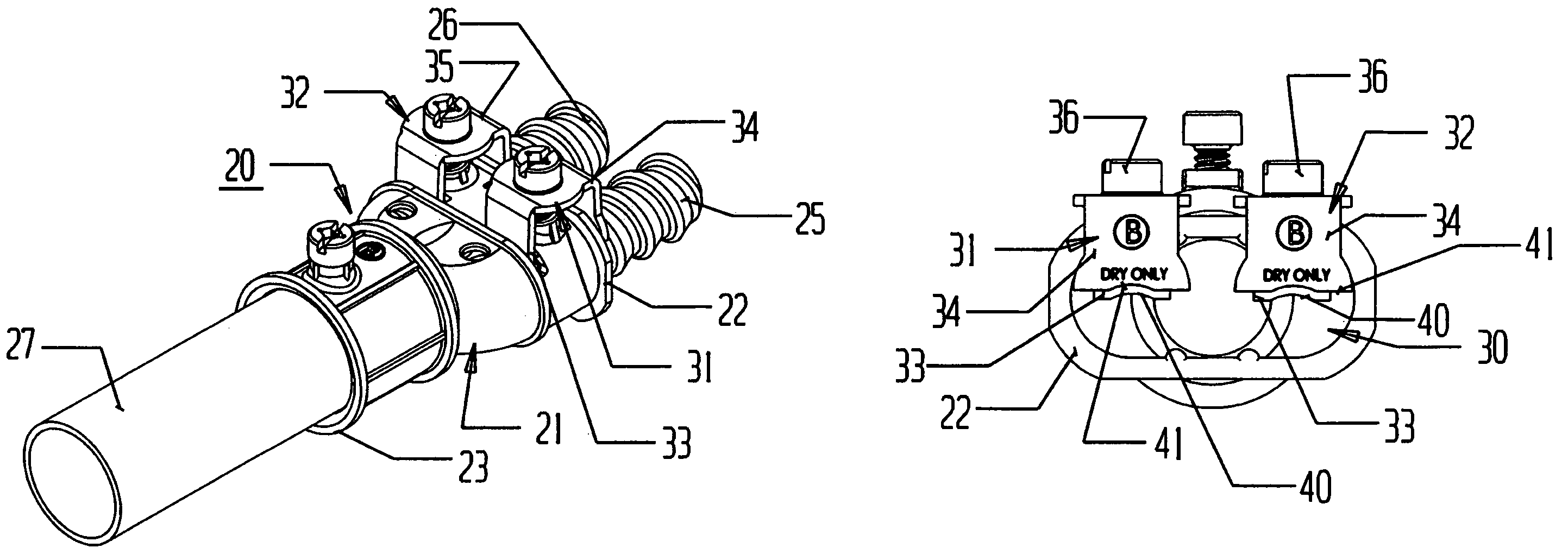
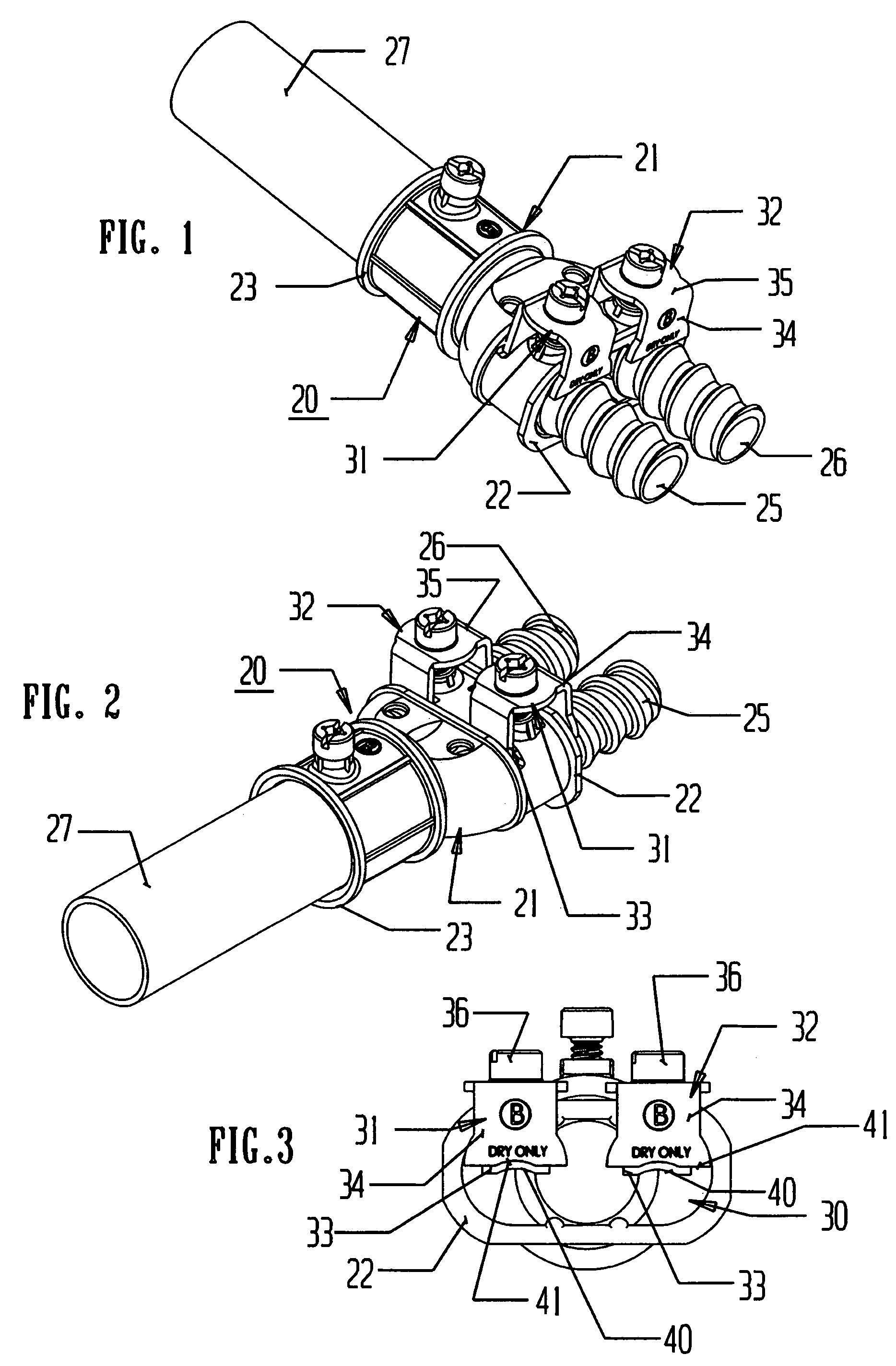
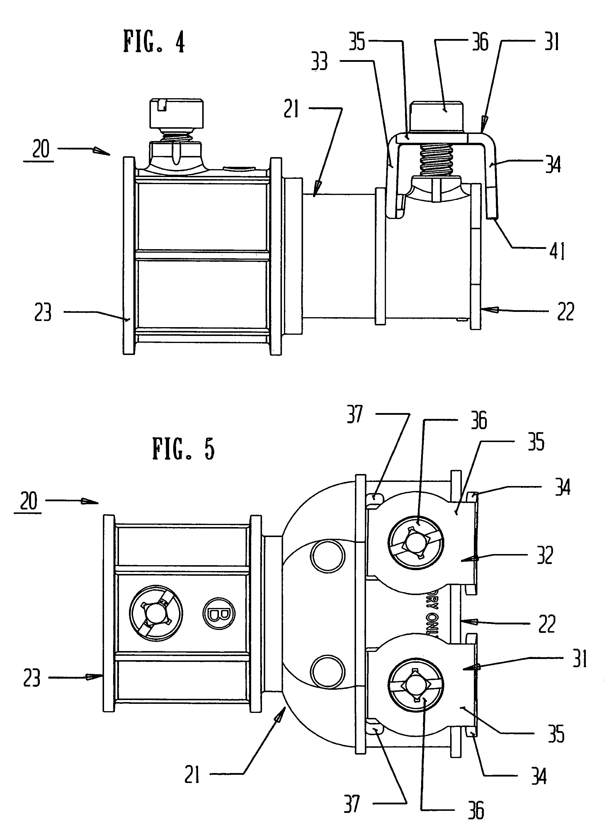
[0040]In FIGS. 1 and 2, dual or duplex conduit / cable connector 20 is depicted incorporating body member 21, front end 22, and rear end 23. In addition, dual / duplex conduit / cable connector 20 is shown with flexible metal conduits and / or armored or metal clad cables 25 and 26 securely mounted to front end 22, while solid or rigid metal tubing or conduit 27 is shown securely affixed to rear ...


PUM


Abstract

By enabling two separate and independent flexible metal conduit and / or armored or metal clad cables to be secured to a single connector for being mounted directly to a single elongated rigid or solid electrical tubing / conduit, an easily manufactured and assembled connector is realized. A dual or duplex conduit / cable connector is constructed for receiving two separate and independent flexible metal conduits and / or armored or metal clad cables and enabling the two conduit / cables to be securely affixed to one end of the connector. The connector preferably incorporates a clamping bracket associated therewith to assure rapid and efficient assembly of the two flexible metal conduits and / or armored or metal clad cables to the duplex connector.

Description

RELATED DATA[0001]This application is a continuation-in-part of U.S. patent application Ser. No. 11 / 713,264, filed Mar. 2, 2007 entitled ELETRICAL CONNECTOR, which is now U.S. Pat. No. 7,402,752, issued on Jul. 22, 2008.TECHNICAL FIELD[0002]This invention relates to electrical connectors, and more particularly, to electrical connectors constructed for securing flexible metal conduits and / or metal clad sheath cables to solid tubing conduits.BACKGROUND ART[0003]In the field of wiring homes and buildings, whether for new construction or for improvements or expansion, substantial development and product improvements have been made. Typically, these improvements are directed to enabling installers to securely mount any desired wiring to any desired location in the most efficient and quickest manner.[0004]In any particular installation or location, various conduits or cables must be interconnected to each other as well as connected to the primary power supply in a suitable power distribut...

Claims


Application Information

Patent Timeline
Patent Type & Authority Patents(United States)
IPC IPC(8): H01R4/00
CPCH01R9/032H02G3/0691H01R9/0524H01R13/65912
Inventor KIELY, KENNETH M.SMITH, LAWRENCE J.
Owner BRIDGEPORT FITTINGS LLC
Why Eureka
Try Eureka