Bead embroidering mechanism of embroidering machine

An embroidery machine and bead embroidery technology, which is applied to the mechanism of the embroidery machine, the embroidery machine, the embroidery machine with automatic control, etc., can solve the problems of low integration, instability, and influence on the work efficiency and stability of the embroidery machine, etc. , to achieve the effect of improving the efficiency of embroidery beads, improving the practicability, and stabilizing the bead body

Active Publication Date: 2015-09-02
SHENZHEN NODROBOT CO LTD
View PDF8 Cites 13 Cited by
  • Summary
  • Abstract
  • Description
  • Claims
  • Application Information

AI Technical Summary

Problems solved by technology

In this utility model, the needle of the embroidery machine passes through the bead hole to embroider the bead body on the clothes. On the basis of the existing embroidery machine equipment, a support frame for placing the beading device is suspended on the beam for placing the thread frame, so that It can continuously provide embroidered beads to the bead guide rod, further connect the bead guide rod to drive the embroidered beads on the bead guide rod to form a bead string device, and a detection device, which can effectively realize the automatic continuous supply of the bead rod, but The supply of embroidery beads by stringing beads is not stable, and the degree of integration with the embroidery machine is not high, which affects the work efficiency and stability of the embroidery beads

Method used


Image

  • Bead embroidering mechanism of embroidering machine
  • Bead embroidering mechanism of embroidering machine
  • Bead embroidering mechanism of embroidering machine

Examples


Embodiment Construction

[0044] The present invention will be described in further detail below in conjunction with the accompanying drawings and specific embodiments.

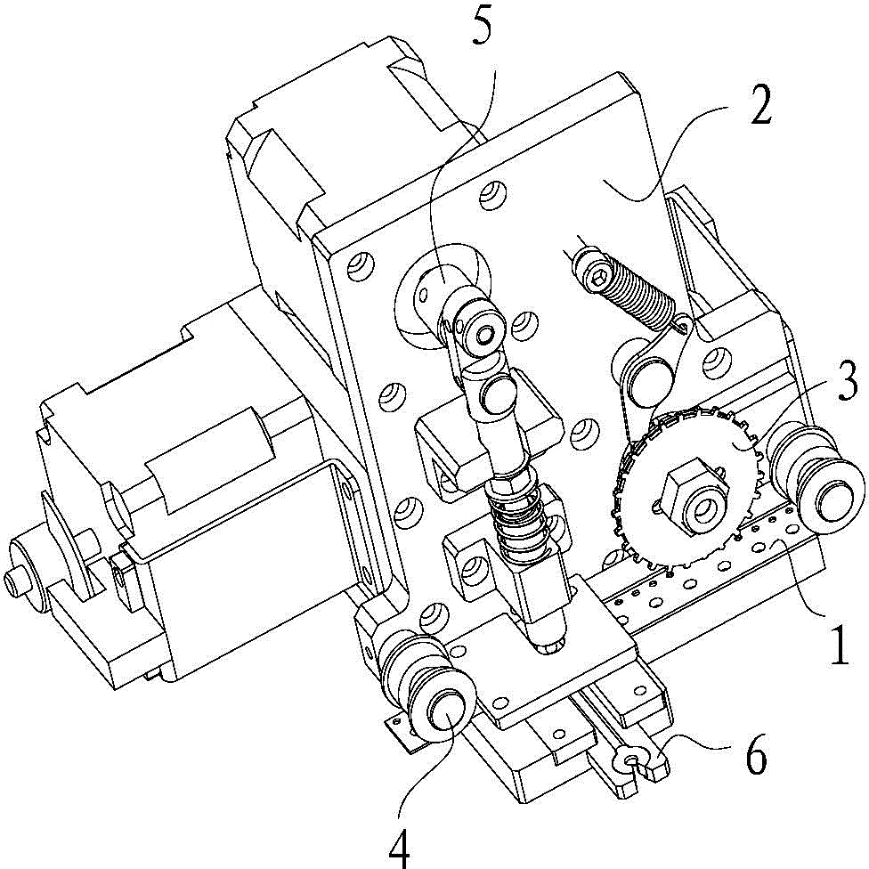
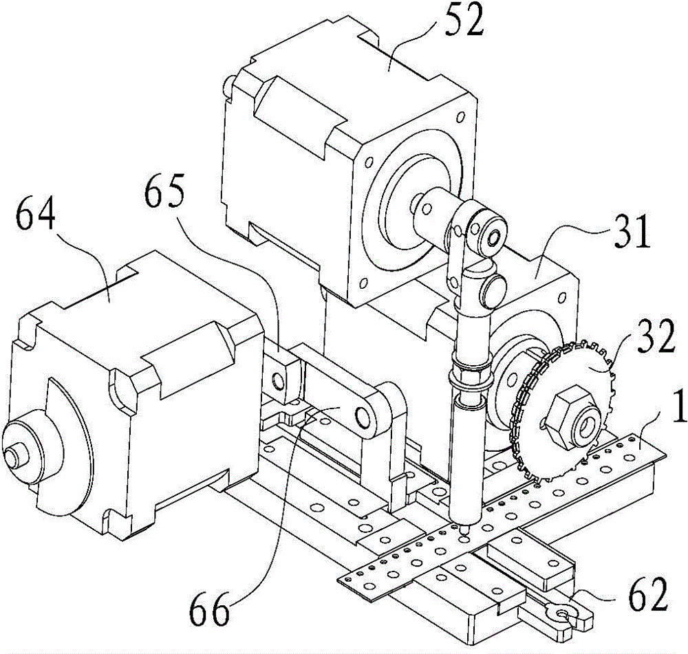
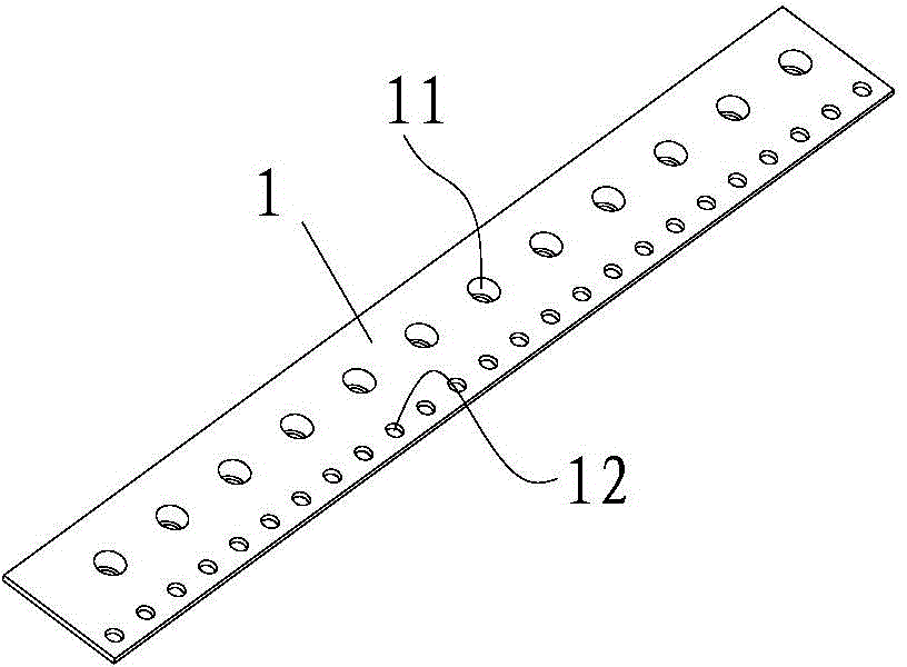
[0045] see figure 1 , figure 2 , Figure 5 , Image 6 and Figure 10 As shown, it is the bead embroidery mechanism of the embroidery machine of the present invention, including the material belt 1, the support 2, the first power unit, the pushing device 5, and the feeding device 6; Arranged and used to place the mounting position of the beads; the first power device is used to drive the material belt 1 to move along its own length; the bracket 2 is provided with a blanking station located on one side of the material belt 1; the pushing device 5 is installed on the On the bracket 2, the pushing device 5 includes a pushing head 51 and a second power device that drives the pushing head 51 to move the beads in the installation position to the blanking station; the feeding device 6 includes a The clamping body 62 of the beads of the ...


PUM


Abstract

The invention provides a bead embroidering mechanism of an embroidering machine. The bead embroidering mechanism comprises a material belt, a first power device, a support, a pushing device and a feeding device, wherein a plurality of mounting positions used for holding beads are longitudinally arranged on the material belt; the first power device is used for driving the material belt to move longitudinally; a discharging position disposed on one side of the material belt is arranged on the support; the pushing device is mounted on the support and comprises a pushing head and a second power device used for driving the pushing head to move so as to push the beads at the mounting positions to the discharging position; the feeding device comprises a clamp for clamping the bead at each discharging position and a third power device used for driving the clamp to move between the discharging position and a position distant from the discharging position, and a first through hole allowing each bead to pass through is formed in the clamp. The bead embroidering mechanism is capable of embroidering the beads efficiently and stably.

Description

technical field [0001] The invention relates to a bead embroidery mechanism of an embroidery machine. Background technique [0002] Embroidering various patterns on clothes can add a lot of color to people's dress. In this era of industrial development, automatic embroidery machines are often used for embroidery, and computer control is used to improve the embroidery speed and stability of embroidery. For some clothes that need to add beads to achieve the three-dimensional decoration effect, the traditional automatic embroidery machine obviously cannot solve the problem of embroidery beads. [0003] Existing, such as the Chinese utility model patent with the publication number CN204265985U and the publication date of April 15, 2015, discloses an embroidery machine that can be used to embroider beads, including a body, an embroidery machine head, and a thread that can be placed. The beam of the frame, the head is provided with an embroidered bead feeding device, and the feed...

Claims


Application Information

Patent Timeline
Patent Type & Authority Applications(China)
IPC IPC(8): D05C7/08D05C13/00
CPCD05C7/08D05C13/00
Inventor 李诺董鹏飞刘进全
Owner SHENZHEN NODROBOT CO LTD
Why Eureka
Try Eureka