Secondary battery winding pin and battery winding method employing the winding pin

A technology for secondary batteries and battery rolls, applied in secondary batteries, secondary battery manufacturing, circuits, etc., can solve problems such as waste of diaphragm, black, and increased curvature, so as to prolong service life, reduce production costs, and save raw materials Effect

Inactive Publication Date: 2009-12-09
BYD CO LTD
View PDF6 Cites 0 Cited by
  • Summary
  • Abstract
  • Description
  • Claims
  • Application Information

AI Technical Summary

Problems solved by technology

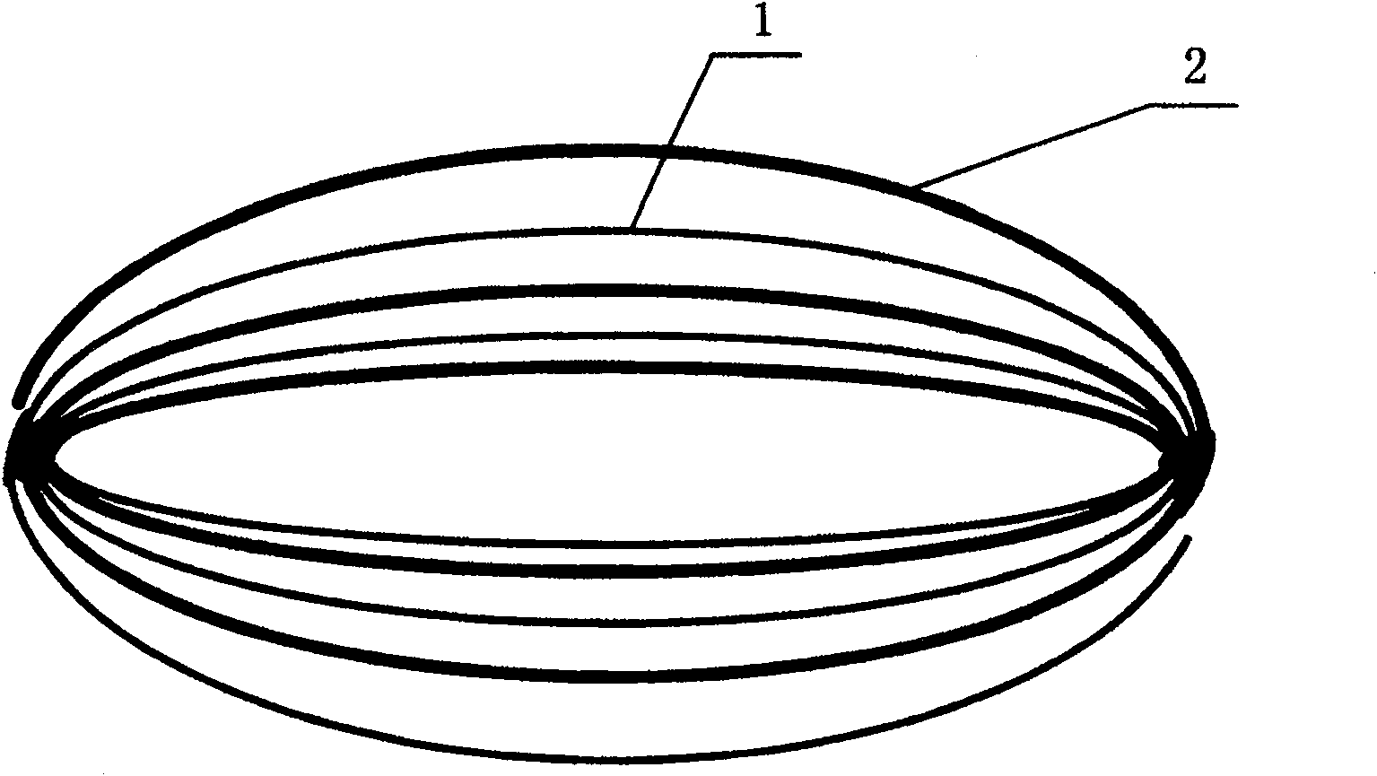
However, there are the following defects: the rolled-out pole core is elliptical, and as the number of winding layers increases, the radian increases (such as figure 1 shown)
Especially after the battery pole core is flattened, the positive and negative electrode sheets 1 and 2 at the corners on both sides of the pole core after flattening cannot fit well due to the larger radian of the outer layer than the inner layer before flattening, and there is a certain gap (such as figure 2 As shown), lithium ions cannot pass through the corner during charging and discharging
As a result, the corner ( figure 2 A position shown in ) cannot be charged, and lithium ions migrate through the joint of the nearest positive and negative electrodes 1 and 2, resulting in the corner edge part ( figure 2 B position shown in ) is overcharged, causing too much lithium ions to accumulate on the negative electrode here, which may produce lithium dendrites, and the surface color of the negative electrode is uneven (that is, the B position at the overcharged position is golden yellow, and even silver-white lithium dendrites are produced. Crystal; while the A position at the corner is graphite black and other undesirable phenomena
In addition, the existing technology must first clamp the diaphragm between the two plates, and then position and wind the positive and negative electrodes 1 and 2 sequentially, resulting in a waste of a circle of diaphragm inside the pole core.

Method used


Image

  • Secondary battery winding pin and battery winding method employing the winding pin
  • Secondary battery winding pin and battery winding method employing the winding pin
  • Secondary battery winding pin and battery winding method employing the winding pin

Examples


Embodiment Construction

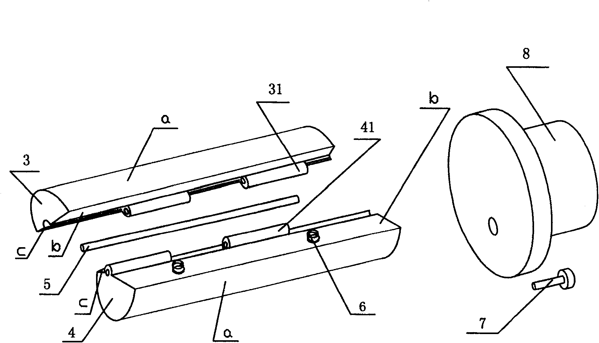
[0028] The secondary battery rolling pin of the present invention is mainly provided with a first member 3 and a second member 4, which are two roughly semi-cylindrical castings, wherein the first member 3 and the second member 4 are formed by arc surfaces a, The columnar body surrounded by the large inclined plane b and the small inclined plane c, the first member 3 and the second member 4 are respectively formed with pivot holes 31, 41 between the respective large and small inclined planes b and c, and the first member 3 When the large and small inclined surfaces b and c of the second member 4 are respectively opposite to the large and small inclined surfaces b and c of the second member 4, pivot shafts 5 are inserted in these pivot joint holes 31 and 41 to form a large jaw E and a small jaw F. A clip-shaped body with two jaws, the periphery of the clip-shaped body is in the shape of a cylinder as a whole. In addition, in the large jaw E formed by the large slope b of the fi...


PUM


Abstract

The present invention relates to a secondary battery rolling pin, which is mainly provided with a first member and a second member, especially the first member and the second member are connected to form a clip-shaped body with two jaws, the clip The periphery of the shape is cylindrical as a whole. The battery winding method using the secondary battery winding needle, especially includes assembling the clip-shaped body on the motor; inserting and clamping the head of the positive electrode sheet into a jaw of the clip-shaped body to start the motor; Turn off the motor at one-third of the week around the clip body, insert and position the negative electrode sheet with a diaphragm on both sides; continue to drive the motor until the positive and negative electrode sheets are all rolled up and stop the motor; finally pull out the clip body. The secondary battery winding needle with this structure is suitable for improving the winding effect of the secondary battery, and the battery winding method using the winding needle with this structure can prolong the service life of the battery and save battery raw materials.

Description

technical field [0001] The invention relates to a secondary battery winding needle and a battery winding method using the winding needle, in particular to a secondary battery winding needle suitable for improving the winding effect of a secondary battery and prolonging the service life of the battery 1. The battery winding method using the winding needle to save battery raw materials. Background technique [0002] Taking the existing lithium-ion battery winding technology as an example, it is a technology that uses two flat plates to clamp the diaphragm first, and then position the positive and negative electrode sheets 1 and 2 for winding. However, there are the following defects: the rolled-out pole core is elliptical, and as the number of winding layers increases, the radian increases (such as figure 1 shown). Especially after the battery pole core is flattened, the positive and negative electrode sheets 1 and 2 at the corners on both sides of the pole core after flatte...

Claims


Application Information

Patent Timeline
Patent Type & Authority Patents(China)
IPC IPC(8): H01M10/04H01M10/40H01M10/0585
CPCY02E60/122Y02E60/10Y02P70/50
Inventor 路宇帅王建军
Owner BYD CO LTD
Why Eureka
Try Eureka