
Bistator single rotor disk type brushless double feed ulternating current electric motor

An AC motor, single-rotor technology, used in electrical components, electromechanical devices, electric components, etc., can solve the problem of low motor power density and power performance index, high motor power density and power performance index, pole number combination and synchronous speed limit and other problems, to achieve the effect of easy realization of structural design, flexible combination of poles, and improved coupling ability

Inactive Publication Date: 2009-12-09
SHENYANG POLYTECHNIC UNIV
View PDF2 Cites 0 Cited by
  • Summary
  • Abstract
  • Description
  • Claims
  • Application Information

AI Technical Summary

Problems solved by technology

[0003] However, due to the existence of the end windings, the long axial length is the main shortcoming of the cascaded brushless doubly-fed AC motor, which limits its popularization and application in some occasions, and the mechanical structure is relatively complicated, but its two sets of stator and rotor The coupling between the windings is good, the power density and force energy index of the motor are high, and there is no limit to the combination of the number of poles of the two motors; the structure of the magnetic field modulation brushless double-fed AC motor is relatively simple, and the axial length is the same as The conventional AC motor is similar, but the coupling between the two sets of windings is poor, the harmonic magnetic field in the motor is rich, and the additional loss is large, so the power density and force energy index of the motor are low, and the number of poles of the two sets of stator windings is required The difference must be greater than or equal to 4, so the combination of the number of poles and the synchronous speed of the motor are limited

Method used


Image

  • Bistator single rotor disk type brushless double feed ulternating current electric motor
  • Bistator single rotor disk type brushless double feed ulternating current electric motor

Examples


Embodiment Construction

[0010] The motor of the present invention will be described in further detail below in conjunction with the accompanying drawings.

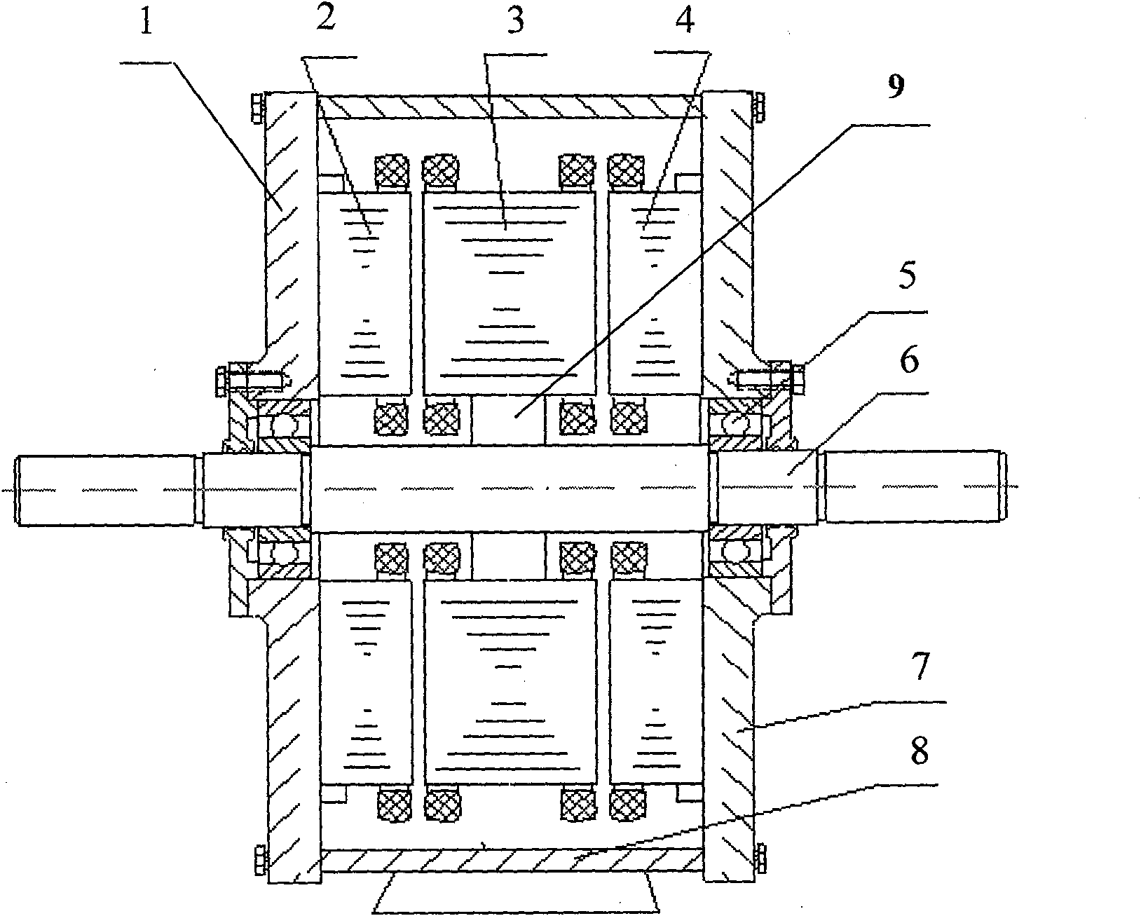
[0011] like figure 1 As shown, the motor of the present invention includes a left end cover 1, a left stator 2, a rotor 3, a right stator 4, a bearing 5, a rotating shaft 6, a right end cover 7, a casing 8, and a rotor support 9. Among them, the left end of the motor shaft 6 is sequentially assembled with a bearing 5 and a left end cover 1 from inside to outside, the left stator 2 is fixed on the left end cover 1, and the right end of the rotating shaft 6 is sequentially assembled with a bearing 5 and a right end cover 7 from inside to outside, and the right stator 4 is fixed. On the right end cover 7, a rotor bracket 9, a rotor 3 and a casing 8 are sequentially assembled in the middle of the rotating shaft 6 along the vertical direction from inside to outside. The left end cover 1, the left stator 2, the casing 8, the right end cover 7, the rig...


PUM


Abstract

A double-stator, single-rotor disc-type brushless double-fed AC motor, including two stators, a rotor, a rotor bracket, a rotating shaft, a bearing, an end cover, and a casing, and the left end of the motor rotating shaft is sequentially assembled with a bearing and a left end Cover, the left stator is fixed on the left end cover, the right end of the shaft is assembled with the bearing and the right end cover from the inside to the outside, the right stator is fixed on the right end cover, and the middle part of the shaft is assembled with the rotor bracket, the rotor and the casing from the inside to the outside in the vertical direction . The rotor core is slotted on both sides to embed two sets of three-phase symmetrical rotor windings with the number of poles 2p and 2q respectively, and then connected in reverse phase sequence or same phase sequence to form a set of rotor windings; the two stator cores are single-sided open The slots are embedded with independent three-phase symmetrical stator windings with 2p and 2q poles respectively. The motor not only has a short axial length and a simple structure, but also has good coupling between the two sets of windings. The power density and force energy index of the motor are high, and there is no limit to the combination of the number of poles of the two sets of stator windings.

Description

technical field [0001] The invention belongs to a motor, in particular to a double-stator, single-rotor disc-type brushless double-fed AC motor. The motor is a general purpose motor, suitable for use as asynchronous motor, synchronous motor and double-fed variable frequency speed regulating motor. It can realize all the functions of wound asynchronous motors and electric excitation synchronous motors under the condition of brushless and reliable. When used as double-fed frequency conversion speed regulation motors, it can realize the use of smaller power frequency converters to drive higher power motors Carry out frequency conversion speed regulation. Background technique [0002] The existing brushless doubly-fed AC motors mainly have two structural types. One is a series-level brushless double-fed AC motor composed of two wire-wound induction motors with different numbers of poles and conventional inner and outer stators and rotors. The rotors of the two motors are mecha...

Claims


Application Information

Patent Timeline
Patent Type & Authority Patents(China)
IPC IPC(8): H02K16/04H02K5/16H02K3/12
Inventor 张凤阁王凤翔王正宗鸣孙广贵
Owner SHENYANG POLYTECHNIC UNIV
Learn More