Ratchet batch

A ratchet and gear technology, applied in the field of ratchet batches, can solve problems such as large minimum rotation angle, inability to loosen screws, and adjustment of forward and reverse directions, etc., and achieve the effect of small rotation angle of ratchet, low cost and few parts

Inactive Publication Date: 2009-12-16
王宁生
View PDF8 Cites 0 Cited by
  • Summary
  • Abstract
  • Description
  • Claims
  • Application Information

AI Technical Summary

Problems solved by technology

[0003] In order to solve the shortcomings of the existing ratchet batches, such as manual adjustment for forward and reverse reversing, loose screws, and large minimum turning angle, the invention provides a ratchet batch, which effectively overcomes the shortcomings of the prior art

Method used


Image

  • Ratchet batch
  • Ratchet batch
  • Ratchet batch

Examples


Embodiment 1

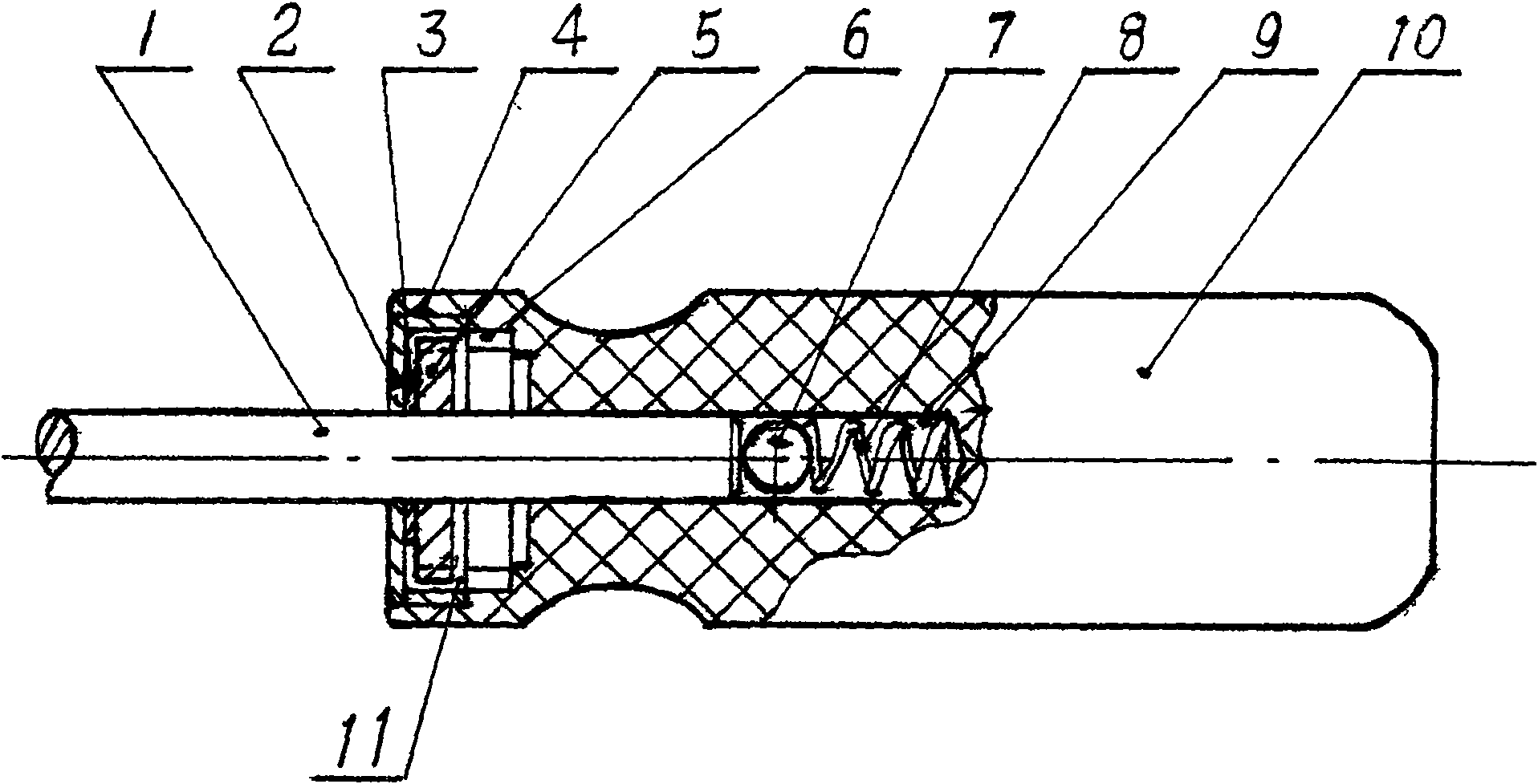
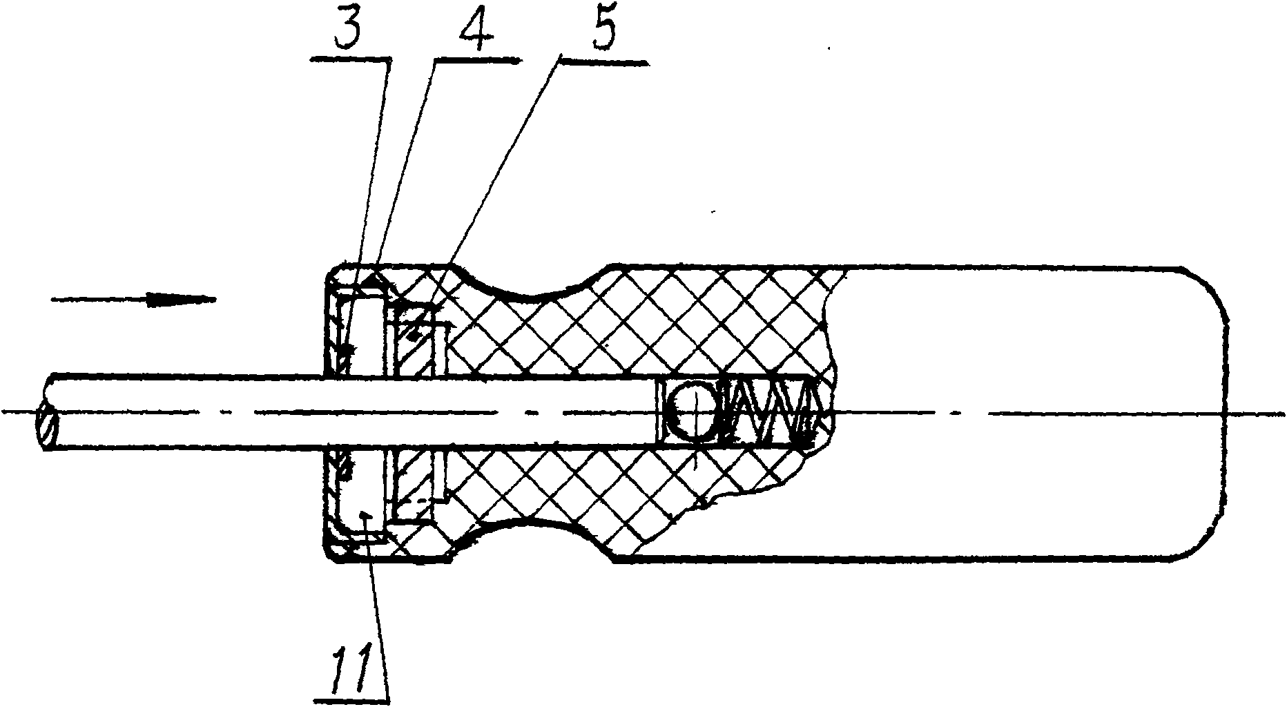
[0015] Such as figure 1 , figure 2 As shown, a gear 5 is provided on the batch rod 1, and the gear 5 is connected with the batch rod 1 as a whole. An end face of the handle 10 is provided with a circular hole 4, and on the inner wall of the circular hole 4 that is greater than a gear thickness from the aperture There is an annular protruding inner ring gear 6 that is fully meshed with each tooth of the gear 5, and a cylindrical cavity 11 is formed between the inner ring gear 6 and the round hole, the gear 5 is located in the round hole 4, and It can reciprocate between the inner ring gear 6 of the round hole 4 and the cylindrical cavity 11; one end of the batch lever 1 is inserted into the round guide hole 9 provided at the inner end of the inner ring gear 6, and the bottom of the round guide hole 9 is in contact with the batch A spring 8 and a steel ball 7 are provided between the end faces of the rod 1; a cover 2 is provided at the mouth of the round hole 4, and a gasket 3...

Embodiment 2

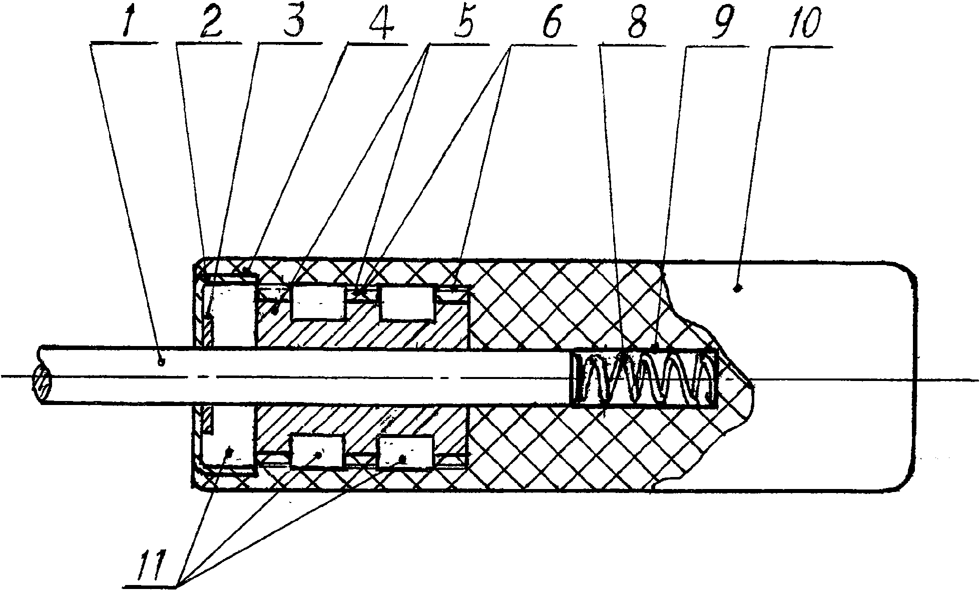
[0019] Such as image 3 , Figure 4 As shown, three identical gears 5 are arranged on the batch rod 1, the intervals between adjacent gears are equal, and the gears and the batch rod 1 are connected as a whole. An end face of the handle 10 is provided with a round hole 4; from a position greater than one gear thickness from the hole, three ring-shaped protrusions are provided on the inner wall of the round hole 4, and each tooth of the gear 5 is fully meshed with each other. Ring gear 6, the interval between adjacent ring gears 6 is the same as the gear interval, and three cylindrical cavities 11 are formed between adjacent ring gears 6 and between the ring gear 6 and the round orifice. Three gears 5 It is located in the round hole 4, and can reciprocate between the inner ring gear 6 of the round hole 4 and the cylindrical cavity 11; one end of the rod 1 is inserted into the circular guide hole 9 provided at the inner end of the inner ring gear 6, and the round A spring 8 is...


PUM


Abstract

The invention discloses a ratchet batch, aiming at providing a ratchet batch, in which a loosening screw can be normally used even without a positive and negative adjusting button and the screw can be randomly unloaded tightly positively and negatively by a single hand with a small screwing angle. The ratchet batch has advantages of large torsion force, small size, simple structure and easy processing and manufacturing. The ratchet batch comprises a rod, gearwheels, annular gears and a spring. The working principle of the ratchet batch is that: the method is applied in the ratchet batch that the gearwheels and the annular gears, both of which have the same number of teeth, are adopted to mesh each tooth of the two gearwheels and the meshed teeth of the two gearwheels are separated axially; with this method, the work performance of the ratchet batch is improved. The invention is applicable for fast unloading tightly the screws on various machineries, electronic equipment and apparatuses.

Description

technical field [0001] The invention relates to a manual tool for tightening and unloading screws, in particular to a ratchet set with large torque and fast operation. Background technique [0002] At present, the known ratchet batch structure is made up of batch bar, small ratchet, ratchet plate, reversing button, handle etc. Because the ratchet is small, the pawl sheet is thin. Therefore, when the force is slightly larger, the teeth often jump, and even the ratchet teeth and pawls are damaged to affect the work. A kind of ratchet screwdriver (00259415.3) etc. as Chinese patent ratchet screwdriver (200520015369.6). As for the forward and reverse reversing, manual adjustment is required, and the ratchet cannot be achieved by loosening the screws, and the minimum turning angle is large. And defects such as many parts, complex mechanism and high cost have also set obstacles for the wide application of ratchet batches. Contents of the invention [0003] In order to solve ...

Claims


Application Information

Patent Timeline
Patent Type & Authority Patents(China)
IPC IPC(8): B25B15/04
Inventor 王宁生王宗孚
Owner 王宁生
Why Eureka
Try Eureka