Ratchet wrench
A technology of ratchet wrench and gear, which is applied in the field of ratchet wrench, which can solve the problems of large minimum turning angle and the failure to ratchet the loose screw by reverse key adjustment, and achieve the effect of small turning angle of the ratchet wheel
- Summary
- Abstract
- Description
- Claims
- Application Information
AI Technical Summary
Problems solved by technology
Method used
Image
Examples
Embodiment 1
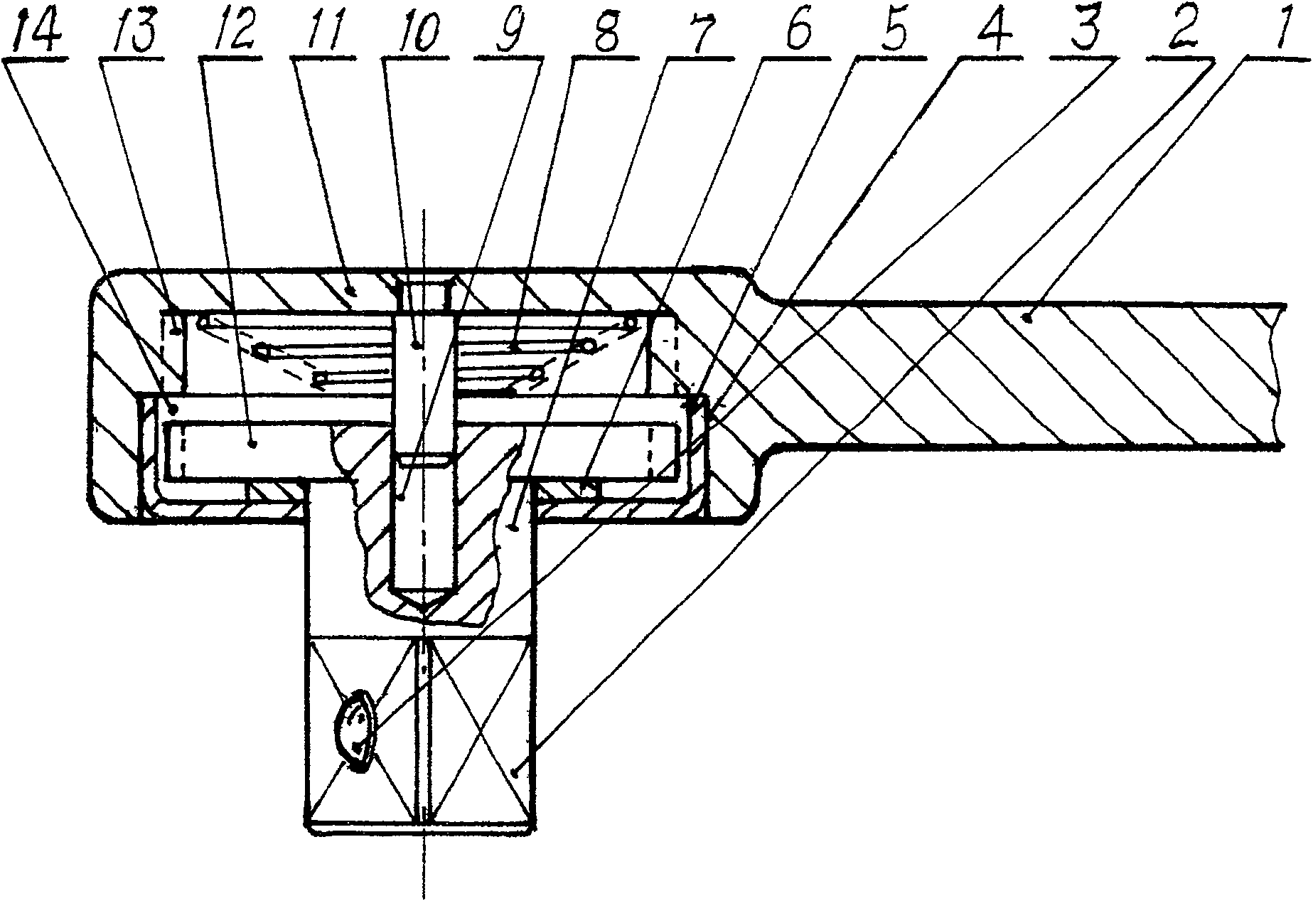
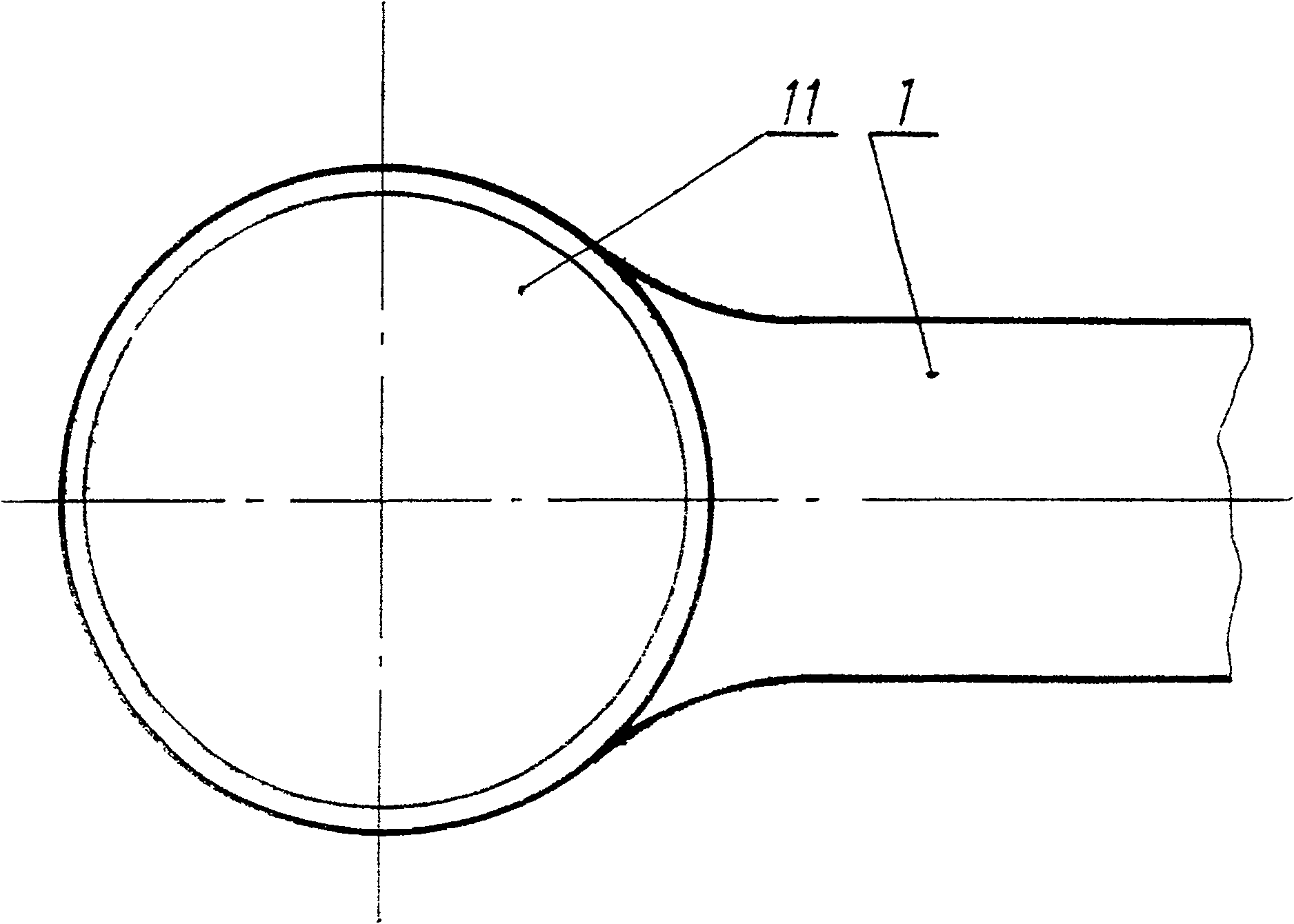
[0014] Embodiment 1: as figure 1 , figure 2 As shown, a square tenon 2 connected to the sleeve head hole is provided at one end of the circular shaft 7, a snap bead 3 is provided on the plane of the square tenon 2, a gear 12 is provided at the other end of the circular shaft 7, and a gear 12 is provided at the other end of the circular shaft 7. One end surface is provided with a round hole 4, and the other end of the round hole 4 is provided with a back cover 11. On the inner wall between the back cover 11 and the round hole 4, there is a ring-shaped protrusion that can mesh with each tooth of the gear on the round shaft 7. The ring gear 13 and the end surface of the back cover 11 are provided with a circular guide shaft 10, and the circular guide shaft 10 is movably matched with the circular guide hole 9 provided on the end surface of the gear 12. A spring 8 is arranged between the back cover 11 and the gear 12, the spring can separate the engaged gear 12 from the ring gear...
Embodiment 2
[0019] Such as Figure 5 , Image 6 As shown, one end of the circular shaft 7 is provided with a hexagonal prismatic tenon 2 connected to the sleeve head hole, and a snap bead 3 is provided on the plane of the tenon 2; the other end of the circular shaft 7 is provided with a gear 12; One end face of the round hole 4 is provided with a round hole 4, and the other end of the round hole 4 is provided with a back cover 11, the back cover 11 is connected with the end face of the inner ring gear by a plurality of screws 15, and the end face of the back cover 11 is provided with a circular guide hole 9, which is connected to the gear The round guide shaft 10 that is provided with on the end face is movable fit. On the inner wall between the bottom cover 11 and the circular hole 4, there is an inner ring gear 13 which protrudes annularly and can mesh with each tooth of the gear on the circular shaft 7. A spring 8 is arranged between the bottom cover 11 and the gear 12, and the spring...
Embodiment 3
[0023] Such as Figure 7 , Figure 8 As shown, one end of the round shaft 7 is provided with a square tenon 2 connected to the sleeve head hole, and a snap bead 3 is provided on the plane of the square tenon 2; the other end of the round shaft 7 is provided with three gears with the same spacing and the same number of teeth. Gear 12; a round hole 4 is provided on one end of the handle 1, and a back cover 11 is provided at the other end of the round hole 4. On the inner wall between the back cover 11 and the round hole 4, there are three annular protruding inner ring gears 13, The three ring gears and the round shaft 7 have the same gear intervals and the same number of teeth, and the three ring gears 13 can mesh with the three gears respectively. A spring 8 is arranged between the bottom cover 11 and the gear 12. The spring can The gear 12 is meshed and separated from the ring gear 13, and the gear 12 is placed in three cylindrical cavities 14 that can idle beside the ring ge...
PUM
 Abstract
Description
Claims
Application Information
 - R&D
- Intellectual Property
- Life Sciences
- Materials
- Tech Scout
- Unparalleled Data Quality
- Higher Quality Content
- 60% Fewer Hallucinations
Browse by: Latest US Patents, China's latest patents, Technical Efficacy Thesaurus, Application Domain, Technology Topic, Popular Technical Reports.
© 2025 PatSnap. All rights reserved.Legal|Privacy policy|Modern Slavery Act Transparency Statement|Sitemap|About US| Contact US: help@patsnap.com


