
Hanging method using C-beam piercing core hanging large-scale electric motor and C-beam structure

A hoisting method and technology for large motors, which are used in the manufacture of motor generators, electrical components, electromechanical devices, etc., can solve problems such as horizontal installation of large motors with insufficient space, and achieve safe and reliable core-piercing process, good economic benefits and social benefits. Benefit, the effect of ensuring the position of the centerline of the motor rotor

Inactive Publication Date: 2009-12-30
TIANJIN 20 CONSTR
View PDF7 Cites 2 Cited by
  • Summary
  • Abstract
  • Description
  • Claims
  • Application Information

AI Technical Summary

Problems solved by technology

[0003] In order to overcome the drawbacks in the above-mentioned prior art, the present invention provides a hoisting method for hoisting a large motor by using a C-shaped beam through the core. The problem of installation can be achieved under the condition that the span of the factory building is smaller than the limit size of the lower core of the motor, and the motor rotor with the added long shaft can be inserted into the inner bore of the motor stator with a bridge crane to hoist the large motor

Method used


Image

  • Hanging method using C-beam piercing core hanging large-scale electric motor and C-beam structure
  • Hanging method using C-beam piercing core hanging large-scale electric motor and C-beam structure
  • Hanging method using C-beam piercing core hanging large-scale electric motor and C-beam structure

Examples


Embodiment Construction

[0022] The hoisting method of the present invention using a C-shaped beam to hoist a large motor through the core will be further described in detail below in conjunction with the accompanying drawings.

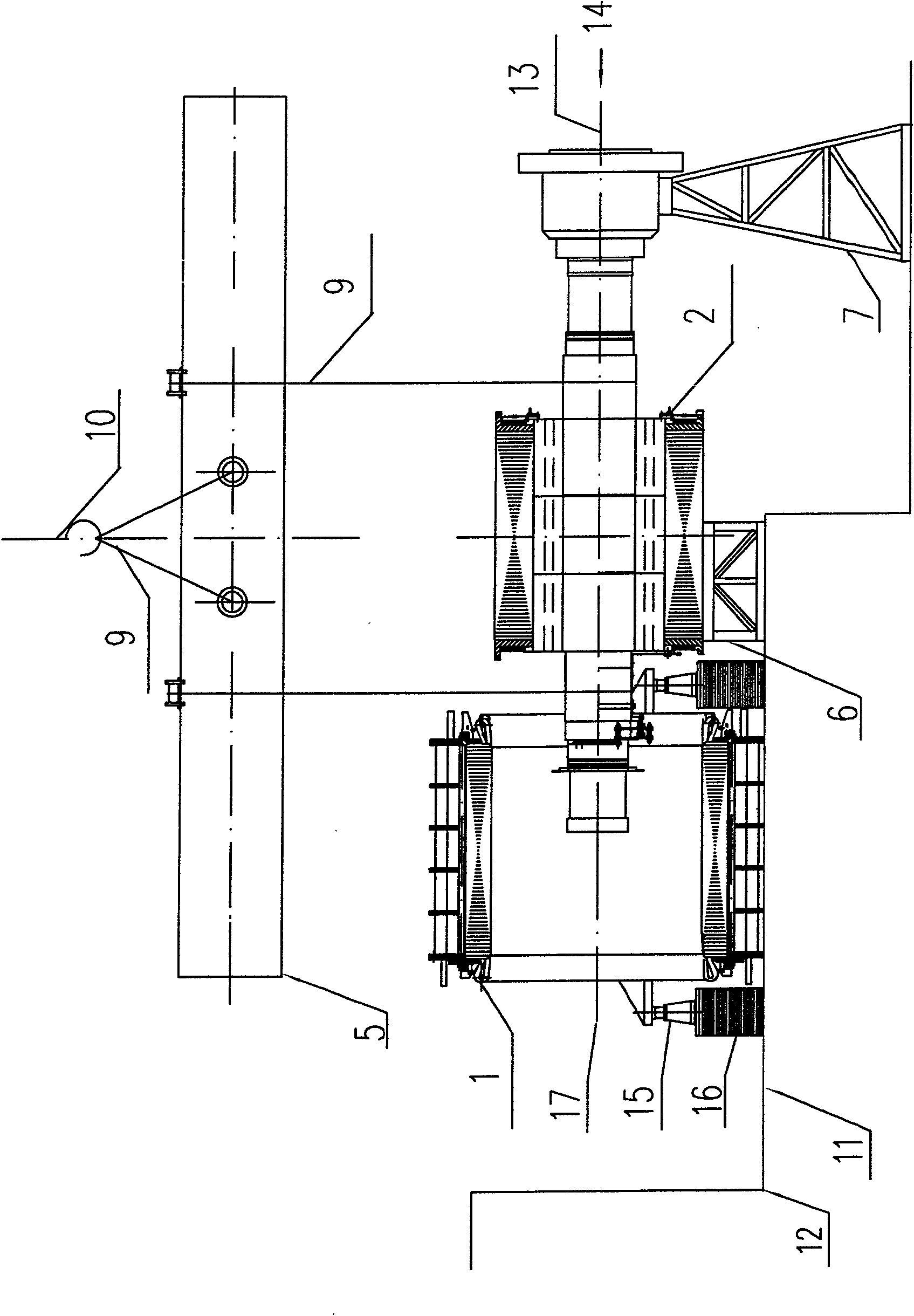
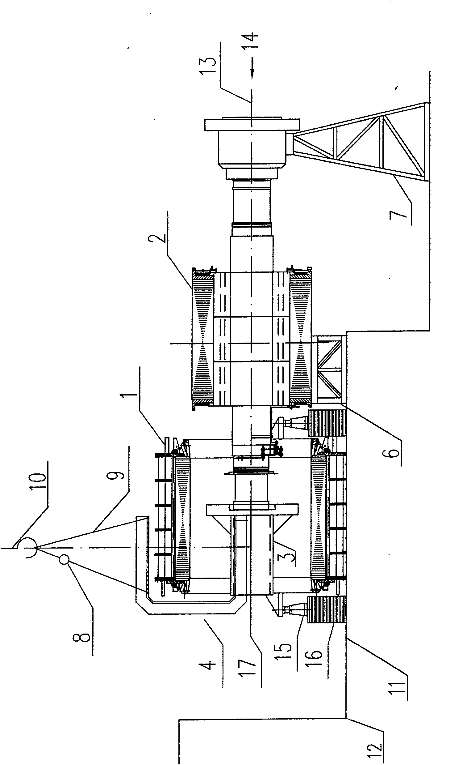
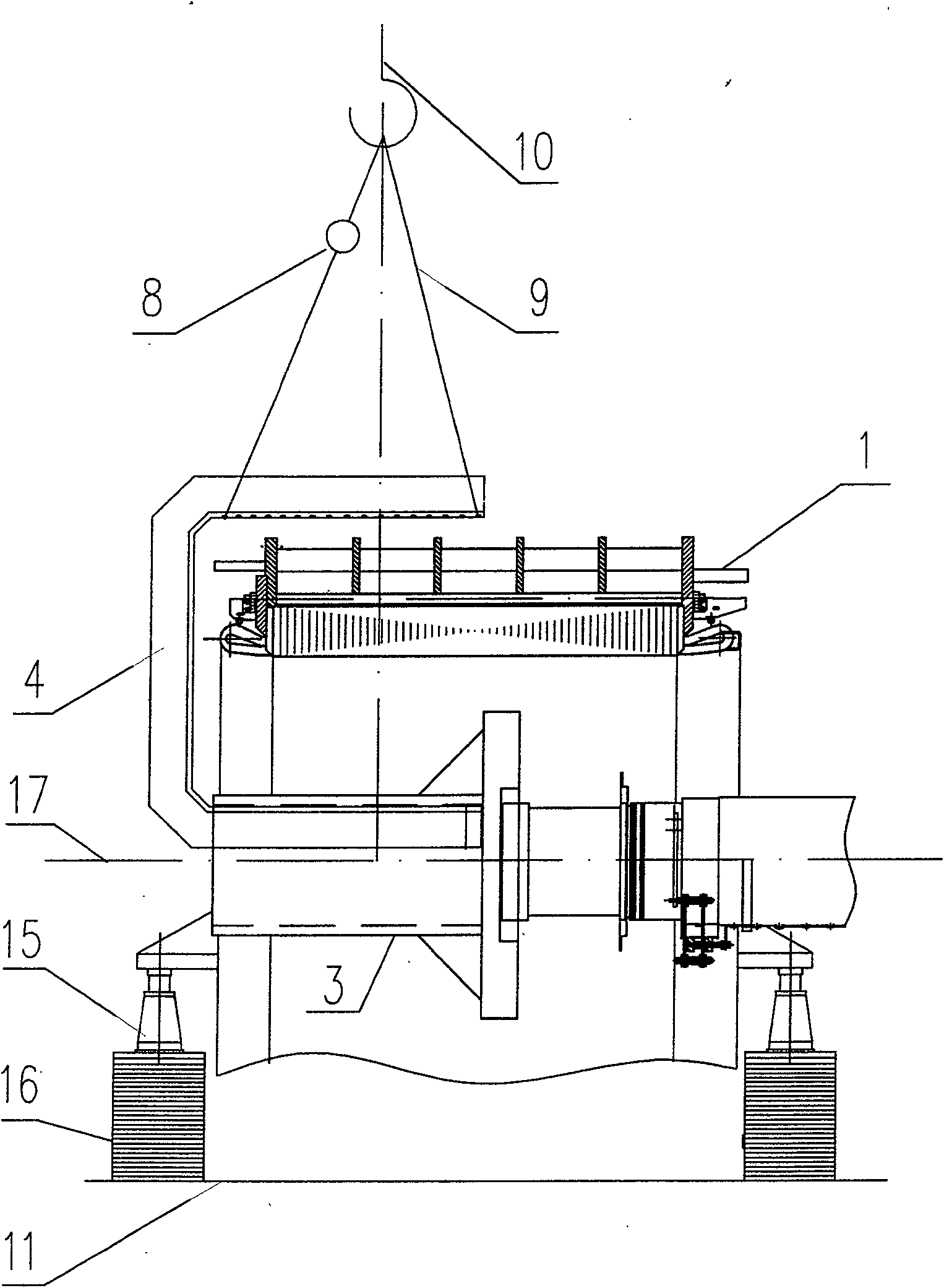
[0023] The C-shaped beam involved in the hoisting method of the present invention, such as Figure 3-1 , Figure 3-2 , Figure 3-3 with Figure 3-4 As shown, the C-shaped beam is welded by steel plates to form a hollow box-shaped structure with equal cross-section. The inner side of the C-shaped beam is provided with a stiffener plate. In order to be more stable and reliable during the hoisting process, a The ribs are provided with arc grooves to facilitate chain rewinding operations. The distance between the inner sides of the upper and lower arms of the C-shaped beam is slightly greater than the maximum radial dimension of the upper part of the motor stator, and the length (referring to the net length) of the upper and lower arms of the C-shaped beam is equal to or sligh...


PUM


Abstract

The invention discloses a hoisting method which adopts a C-shaped beam to hoist a large-sized electric motor through a core-piercing way. The invention comprises the steps that: a hoisting rotor is arranged at the front end of an electric motor base and is stabilized through a support; after hoisting a stator, the side axle of the non-transmission end of the rotor protrudes into a stator chamber and is positioned on a support of a base plate; the axial center line of the stator chamber is adjusted to overlap with the axial center line of the rotor; the extended shaft is hoisted and connected through the C-shaped beam in the core-piercing way: the extended shaft is hoisted after being leveled and is penetrated into the stator chamber and is connected with the non-transmission end of the rotor; when the extended shaft protrudes out of the stator, the rotor is positioned on a support frame; the rotor is leveled again and hoisted, and the rotor penetrates into the stator through the control of a crane; when the extended shaft reaches the spatial extreme place, temporarily the rotor is positioned in the stator chamber; then the extended shaft is disassembled through the crane and the rotor is hoisted and core-pierced to a proper place; after the core-piercing of the rotor, the stator and the rotor simultaneously fall to the proper place, and preparation for landing is made; and slowly the stator and the rotor fall on the base plate and a bearing seat respectively.

Description

technical field [0001] The invention relates to a hoisting method for hoisting a large-scale motor, in particular to a hoisting method for hoisting a large-scale motor for a metallurgical four-roller plate rolling mill by using a C-shaped beam through the core. Background technique [0002] In the metallurgical industry, the double main drive motor used in the four-high plate mill is generally installed horizontally in the main electric room, that is, the motor stator is put in place first, and then the motor rotor is connected to the long shaft, and then penetrated into the motor stator. in-bore approach. At present, the double main drive motors of the four-high plate mill are generally installed horizontally in the main electric room span. There is only one bridge-type crane for equipment installation and maintenance in the span of the main electrical room. When the arrangement is such that the lower roll motor is in front (closer to the rolling mill, the front) and the u...

Claims


Application Information

Patent Timeline
Patent Type & Authority Patents(China)
IPC IPC(8): H02K15/00B66C1/10
Inventor 周进书陈儒科曹跃进
Owner TIANJIN 20 CONSTR
Learn More