
Electronic apparatus shockabsorbing device

A technology for electronic equipment and shock absorption device, which is applied in transportation and packaging, non-rotational vibration suppression, vehicle parts, etc. The effect of avoiding direct contact and reducing costs

Inactive Publication Date: 2010-01-06
北京英特诺科技有限公司
View PDF8 Cites 0 Cited by
  • Summary
  • Abstract
  • Description
  • Claims
  • Application Information

AI Technical Summary

Problems solved by technology

[0004] The purpose of the present invention is to provide a shock absorbing device for electronic equipment, so as to overcome the disadvantage that electronic equipment with low anti-seismic performance cannot be placed in motor vehicles in the prior art

Method used


Image

  • Electronic apparatus shockabsorbing device
  • Electronic apparatus shockabsorbing device
  • Electronic apparatus shockabsorbing device

Examples


Embodiment 1

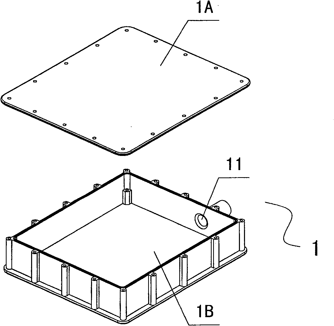
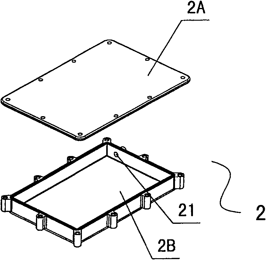
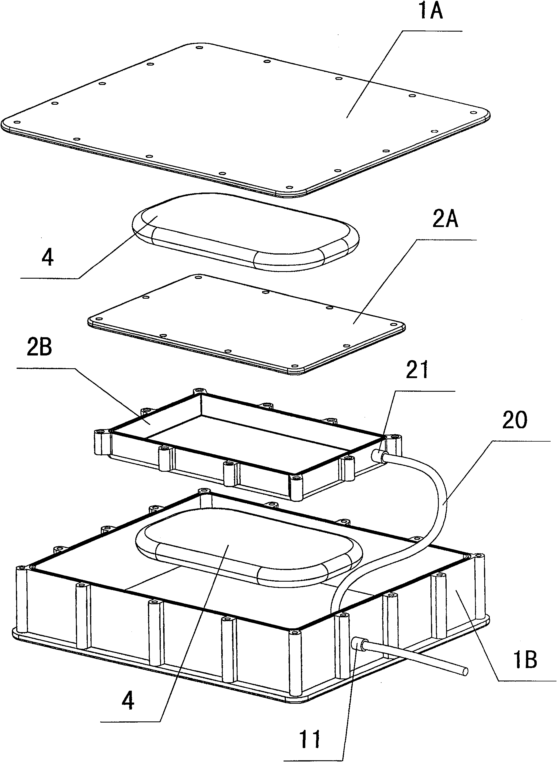
[0042] according to figure 1 , figure 2 and image 3 , the present invention includes a first container 1, and a second container 2 smaller in volume than the first container 1, wherein, as figure 1 As shown, the first container 1 includes a first cover plate 1A and a first box body 1B, such as figure 2 As shown, the second container 2 includes a second cover plate 2A and a second box body 2B.

[0043] Both the first container 1 and the second container 2 offer cable interfaces 11, 21 that can prevent leakage, such as Figure 4 As shown, the cable interface 11 is opened on the first box body 1B, as Figure 5 As shown, the cable interface 21 is opened on the second box body 2B.

[0044] Such as image 3 As shown, the electronic equipment (hard disk) is connected to the hard disk through the cable interface 11, 21 using the cable 20, and passes through the cable interface 21 and the cable interface 11 in turn to communicate with the outside. Obviously, the hard disk can ...

Embodiment 2

[0050] according to Figure 4 and Figure 5 , the main difference between this embodiment and embodiment 1 is: in this embodiment, a spring 5 is also connected between the second container 2 and the first container 1, such as Figure 4 As shown, the four corners outer ends of the second box body 2B offer hanging holes 22, similarly, the four corners inner ends of the first box body 1B are also provided with corresponding hole positions, like this, as Figure 5 As shown, four springs 5 ​​are connected between the second container 2 and the first container 1, and the four springs 5 ​​are connected at four diagonal positions between the second container 2 and the first container 1. The elastic coefficient of the springs 5 It should be as low as possible. Taking the automotive environment as an example, the value of the spring 5 is preferably such that the time constant of this embodiment can be maintained in the range of "seconds" to avoid resonance.

[0051] The structures and...


PUM


Abstract

A damping device of electric equipment for relating to engineering element, its character lies: including the first container and the second one of which cubage is smaller than the first one, and the second container is fixed in the first one be full of liquid, and electric equipment in the second one. Both of container are equipped with join-mouth of electric wire and cable preventing leakage.The electric equipmemt connects with outside through join-mouth of electric wire and cable, the second container also provided with air trap filled in air which cohere both side of the second container.,and the air trap is made of silica gel. At least two spring is installed between both of container; the electric equipment as a hard disk adopts wireless or wired way to communicate to outside. The present invention has seismic performance, and practical, high reliability.

Description

technical field [0001] The invention relates to engineering components, in particular to a shock absorbing device for electronic equipment. Background technique [0002] When the car is running on the road, due to the unevenness of the road, the car is subjected to great vibrations, and the higher the speed, the greater the vibration. Although the motor vehicle industry has invested huge research and development costs in shock absorption, since shock absorption usually has a negative impact on the handling performance of the vehicle, and eventually even affects driving safety, there is limited room for improvement. At present, the instantaneous peak of vehicle vibration The value is still stuck around 40g. [0003] Due to the short time, this instantaneous value has little impact on passengers, but it may cause huge damage to electronic equipment. Therefore, in the prior art, some electronic equipment with low anti-seismic performance cannot be placed in motor vehicles. am...

Claims


Application Information

Patent Timeline
Patent Type & Authority Patents(China)
IPC IPC(8): F16F15/02B60R11/00
Inventor 吴坦
Owner 北京英特诺科技有限公司
Learn More