Split piston for an internal combustion engine

An internal combustion engine, multi-part technology, applied in the direction of pistons, cylindrical pistons, plungers, etc., can solve the problems of time-consuming and labor-intensive assembly of pistons, and achieve the effect of reliable assembly

Inactive Publication Date: 2010-01-20
MAHLE GMBH
View PDF7 Cites 0 Cited by
  • Summary
  • Abstract
  • Description
  • Claims
  • Application Information

AI Technical Summary

Problems solved by technology

This has the following disadvantages: the assembly of known pistons is very time-consuming and labor-intensive

Method used


Image

  • Split piston for an internal combustion engine
  • Split piston for an internal combustion engine

Examples


Embodiment Construction

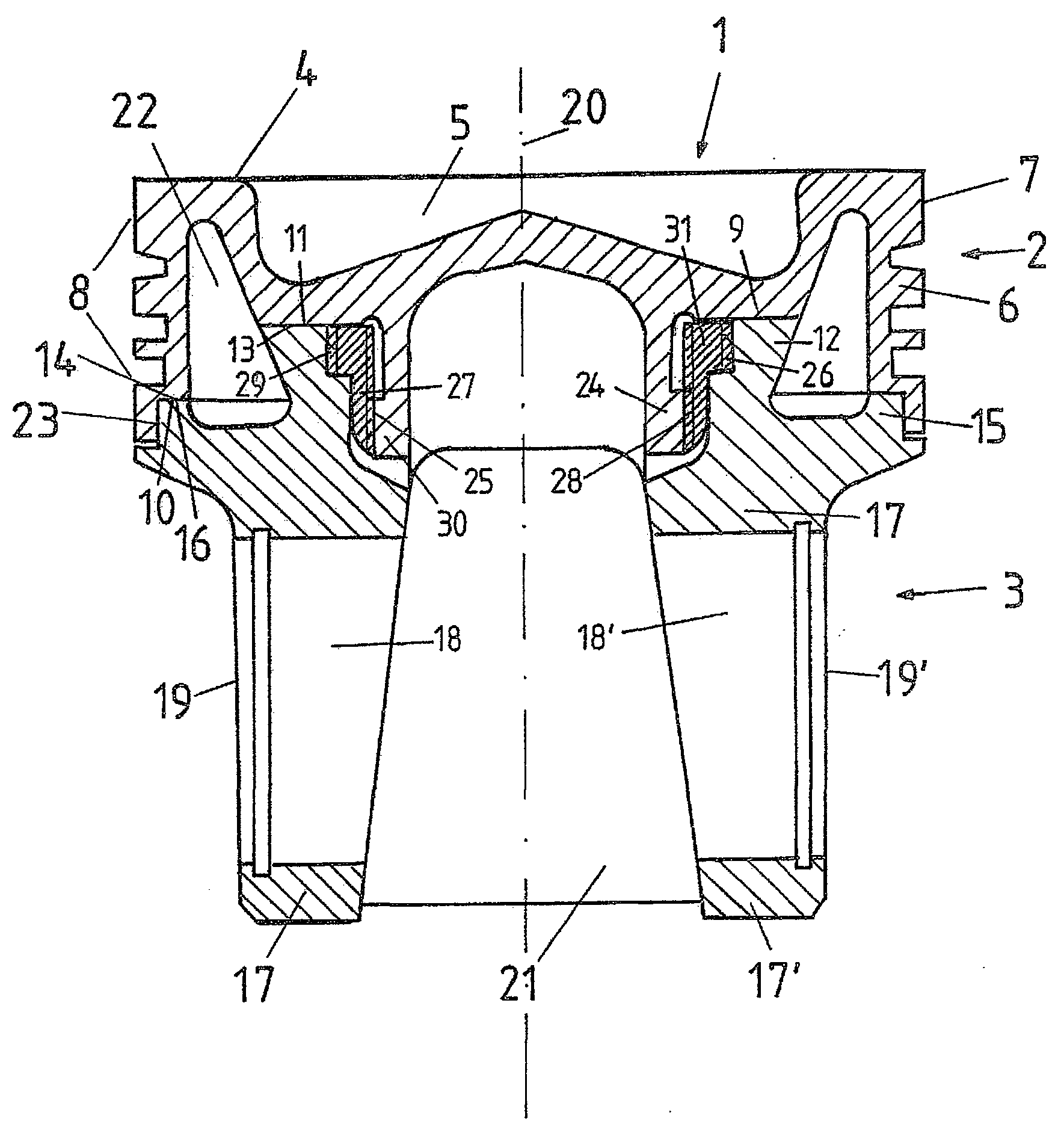
[0039] figure 1 A multi-part cooling piston is described, consisting of an upper part 2 and a lower part 3 . The upper part 2 and the lower part 3 are made of steel. The piston crown 4 is formed by the piston top, which has a combustion chamber 5 in the inner region. Formed on the outer edge of the piston crown 4 is an annular wall 6 whose outer surface on the piston top side forms a fire land, next to the fire land is an annulus 8, which is provided with a ring for receiving, not shown in the figure. The annular groove of the piston ring.

[0040] Two piston pin seats 17, 17' each with a piston pin hole 18, 18' are arranged on the side of the lower part facing away from the piston top 4, and the end faces 19, 19' of the piston pin seat are facing the piston relative to the ring wall The direction of the longitudinal axis 20 is set inwardly. The piston skirt element 21 is connected to the piston pin seats 17 , 17 ′ and to the lower part 3 of the piston 1 .

[0041] The up...


PUM


Abstract

A split piston (1), for an internal combustion engine is disclosed, comprising an upper piece (2), connected to a lower piece (3), by means of a screw connection. The screw connection comprises a tubular connector piece (24), mounted on the underside of the piston upper piece (2) with an external thread (25), a spacer sleeve (27) with an external (29) and an internal (28) thread and a support rib (12) formed on the lower piece (3) of the piston (1) with an internal thread (26). The upper piece (2) can thus be screwed to the lower piece (3), by means of the connector piece (24), the spacer sleeve (27) and the support rib (12). The spacer sleeve (27) acts as a compressing body and the connector piece (24) as an extending body, to generate the mechanical tension necessary for fixing the screw connection.

Description

technical field [0001] The invention relates to a multi-part piston for an internal combustion engine comprising an upper part with a piston crown, on which a ring wall with a ring is formed, and a lower part, which is threaded The connection is connected to the upper part and has a piston pin seat with a piston pin hole and a piston skirt element connected to the piston pin seat on its bottom surface facing away from the upper part. Background technique [0002] German patent 969 838 discloses a multi-part internal combustion engine piston consisting of a piston body and a bottom connected to the body by means of tightening screws. In order to ensure a reliable threaded connection under these conditions and during the rapid reciprocating movement of the piston, the mounting of the base to the piston body requires a considerable amount of tightening of the screws. This has the disadvantage that the assembly of known pistons is very time-consuming and labor-intensive. Cont...

Claims


Application Information

Patent Timeline
Patent Type & Authority Patents(China)
IPC IPC(8): F02F3/00F16J1/00
CPCF02F3/0023F16J1/005F02F3/00F16J1/00
Inventor 米夏埃尔·乌尔里希
Owner MAHLE GMBH
Why Eureka
Try Eureka