

Timer control method and system
A control method and timer technology, applied to electrical components, telephone communications, etc., can solve problems such as poor user service quality, waste of resources, and inability to apply business conversations, and achieve the effect of avoiding abnormal termination and saving network resources
- Summary
- Abstract
- Description
- Claims
- Application Information
AI Technical Summary
Problems solved by technology
Method used
Image

Examples
Embodiment Construction
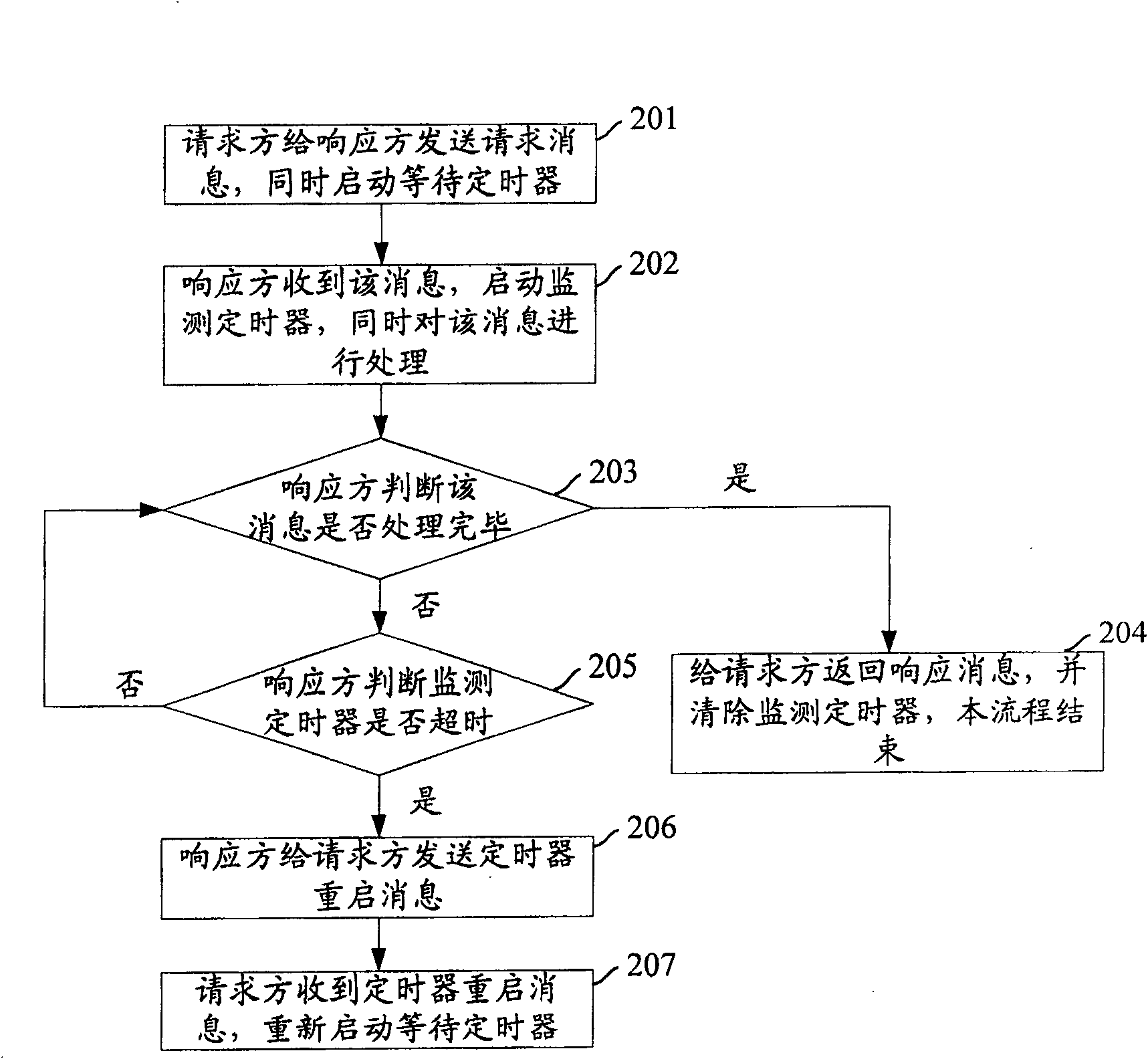
[0026] The core idea of the present invention is: when the requesting party sends a request message to the responding party, it starts a waiting timer; after the responding party receives the message, it starts a monitoring timer, and the duration of the monitoring timer is less than the duration of the waiting timer. When the responder has not finished processing the request message but the monitoring timer expires, the responder sends a timer restart message to the requester; after receiving the message, the requester restarts the waiting timer to continue waiting for the response from the responder.
[0027] The present invention will be further described in detail below in conjunction with the accompanying drawings and specific embodiments.
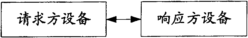
[0028] figure 1 It is a system block diagram of timer control provided by the present invention, such as figure 1 As shown, it specifically includes:
[0029] The requester device: used to send a request message to the responder d...
PUM
 Abstract
Description
Claims
Application Information