

Golf club head counterweight structure able to absorb shock
A technology for golf club heads and counterweights, which is applied to golf balls, golf clubs, rackets, etc., and can solve problems such as abnormal sound when hitting the ball, small damping, and poor shock absorption
- Summary
- Abstract
- Description
- Claims
- Application Information
AI Technical Summary
Problems solved by technology
Method used
Image

Examples
Embodiment Construction
[0031] In order to make the above and other objects, features and advantages of the present invention more clearly understood, preferred embodiments of the present invention will be exemplified below and described in detail in conjunction with the accompanying drawings.
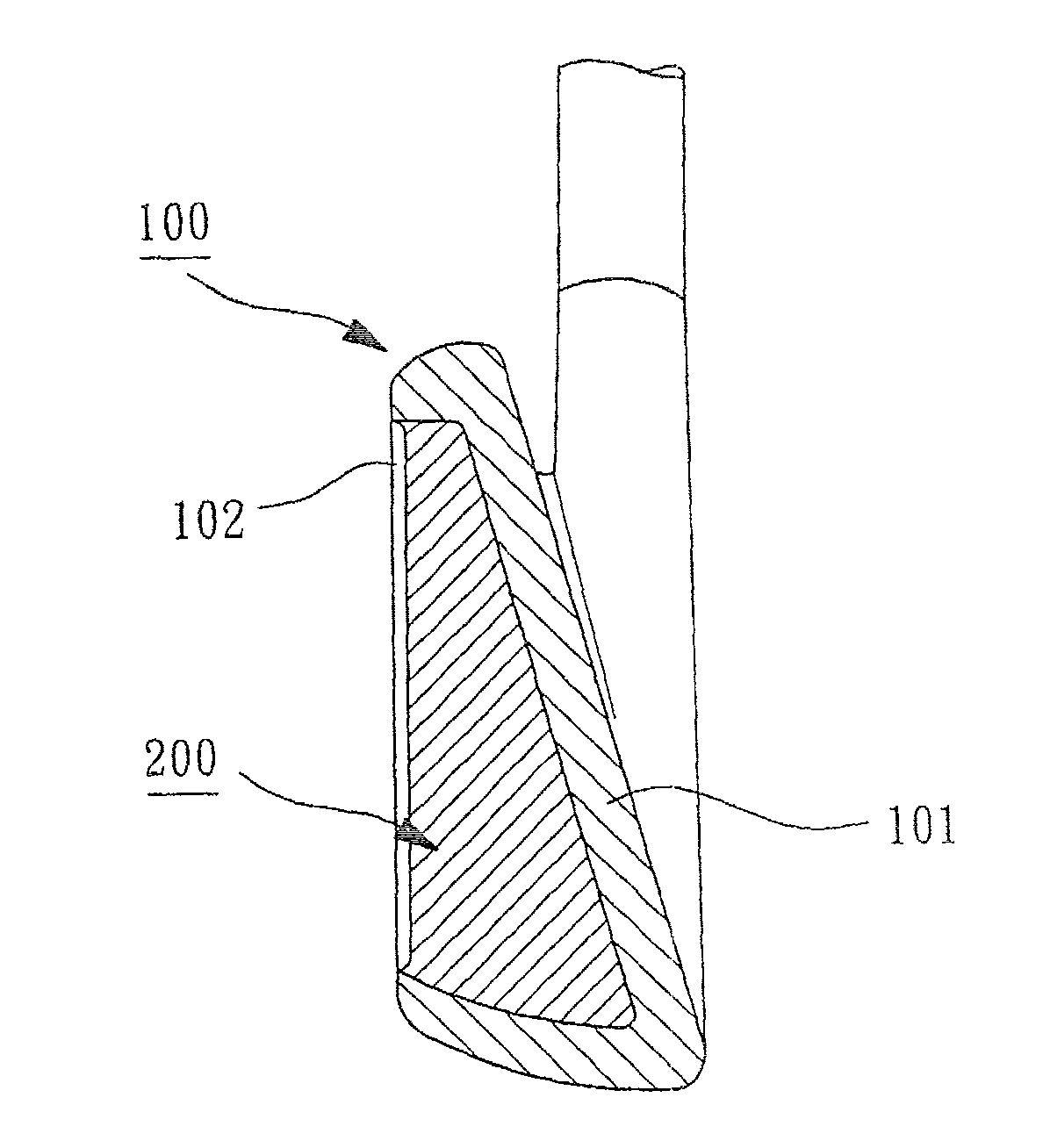
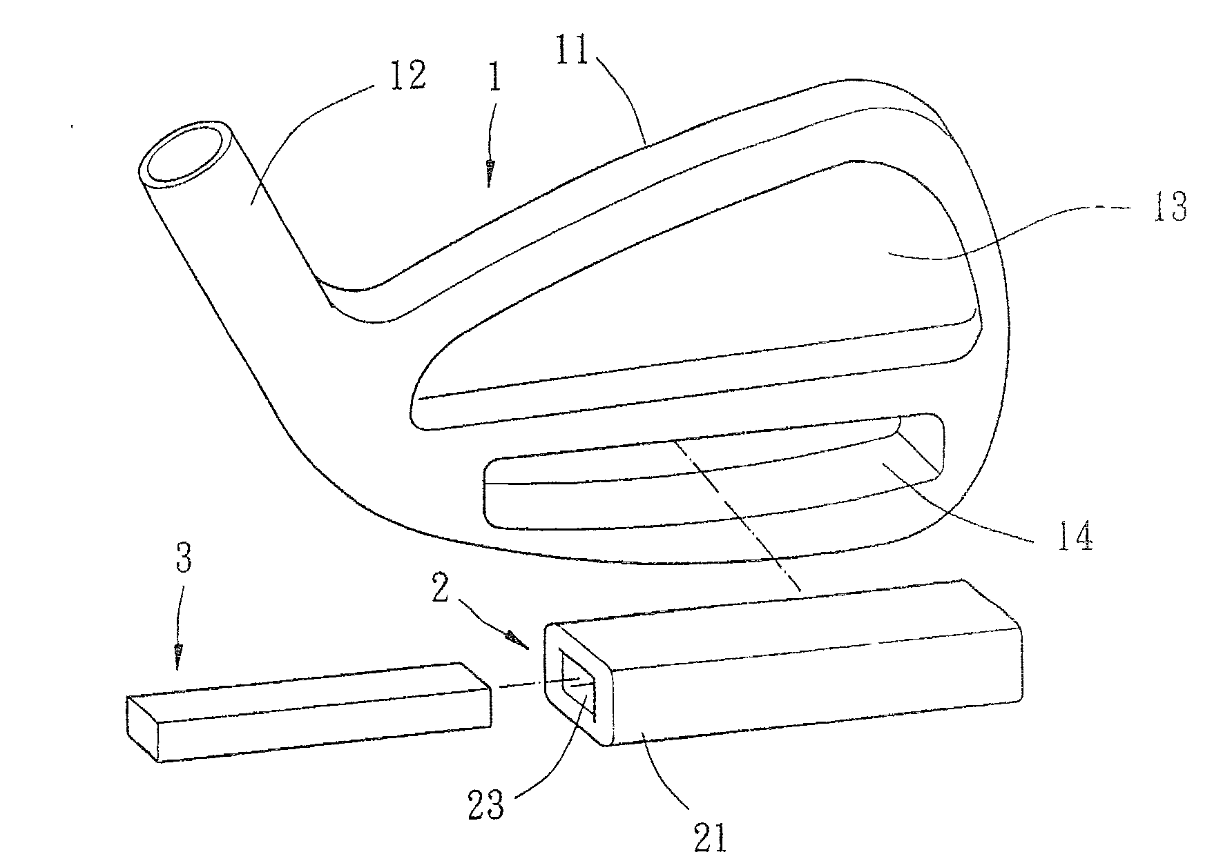
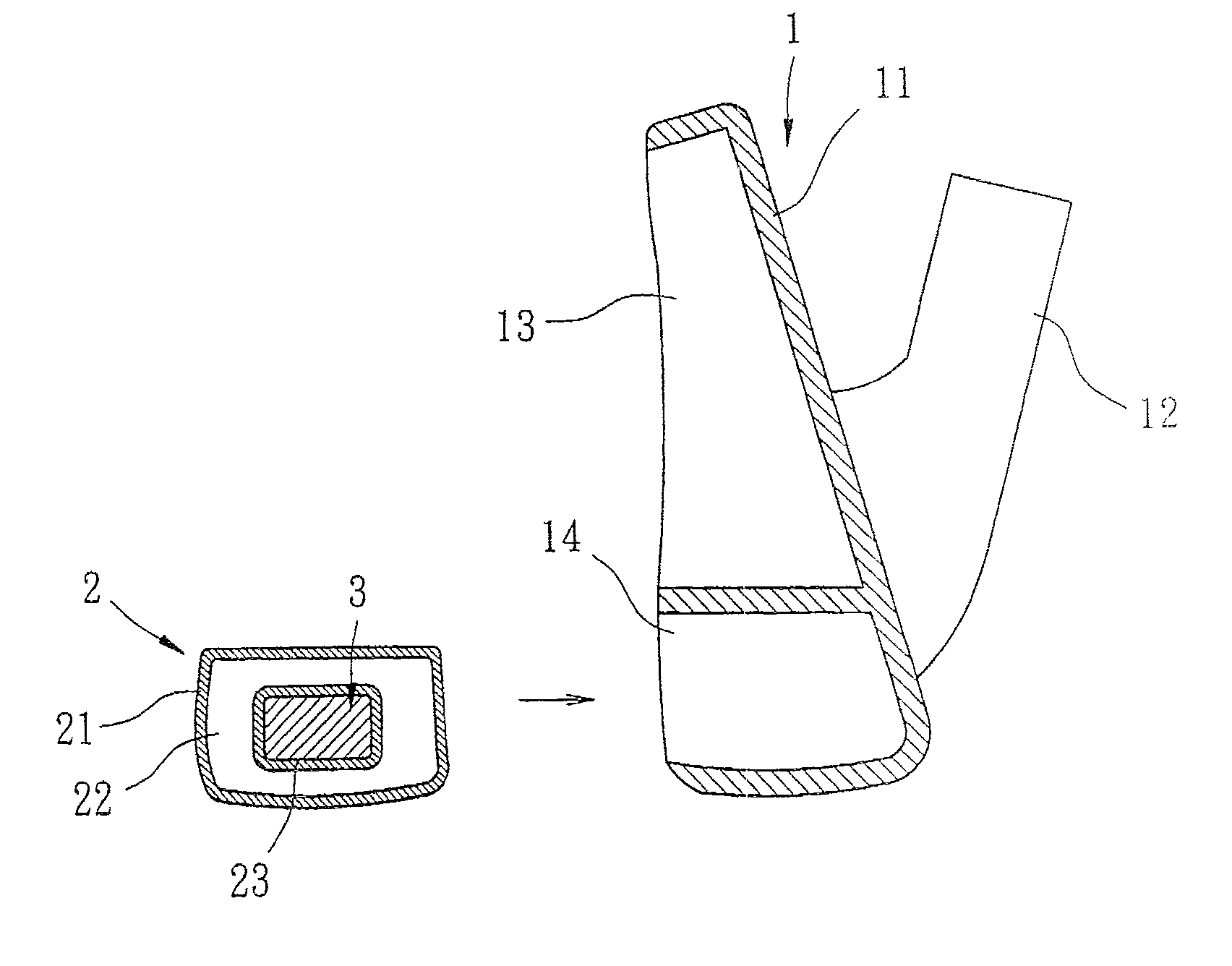
[0032] Please refer to figure 2 As shown, the shock-absorbing golf club head counterweight structure according to the first embodiment of the present invention includes a club head body 1 , at least one elastic air cushion 2 and at least one counterweight 3 . The club head body 1 is an iron club head structure, which is provided with a striking panel 11, a set of neck 12, a back cavity 13 and a containing chamber 14 (vibration control area). The front of the club head body 1 can be welded, brazed, embedded, screwed or integrally formed to form the hitting panel 11, and the hitting panel 11 can be used for hitting golf balls. The collar 12 is arranged on one side of the striking panel 11, the side of the clu...
PUM
 Abstract
Description
Claims
Application Information