
Automatic woven tape winding machine

A coiling machine and webbing technology, which is applied in textile, knitting, and strip winding, can solve the problems of increasing labor intensity, reducing efficiency, and increasing equipment investment, so as to save manpower and material investment, improve work efficiency, and reduce The effect of production costs

Active Publication Date: 2010-02-17
HEBEI HONGDE PLASTIC HARDWARE PROD
View PDF6 Cites 0 Cited by
  • Summary
  • Abstract
  • Description
  • Claims
  • Application Information

AI Technical Summary

Problems solved by technology

[0002] At present, whether the tape winding machines on the market are fully automatic or semi-automatic, they can generally only wind a single tape at a time. The machine is driven by a frequency conversion motor through a transmission mechanism to rotate the reel (only a single reel can be placed). The adjustment mechanism and the wire arrangement mechanism are wound on the reel, but for the ribbon equipment that produces multiple ribbons at a time, if this kind of ribbon winding machine is configured, only one ribbon can be wound at a time, and the rest of the ribbons can only be piled up, which cannot meet the requirements. Its production requirements, therefore, a loom needs to be equipped with many winding machines, which not only increases equipment investment, but also may cause the equipment to be idle. Some of them can only use semi-automatic winding machines because the site cannot meet the requirements, which increases the number of workers working overtime. Wrapping the packaging greatly reduces the efficiency, which not only increases the labor intensity of the workers, but also increases the production cost

Method used

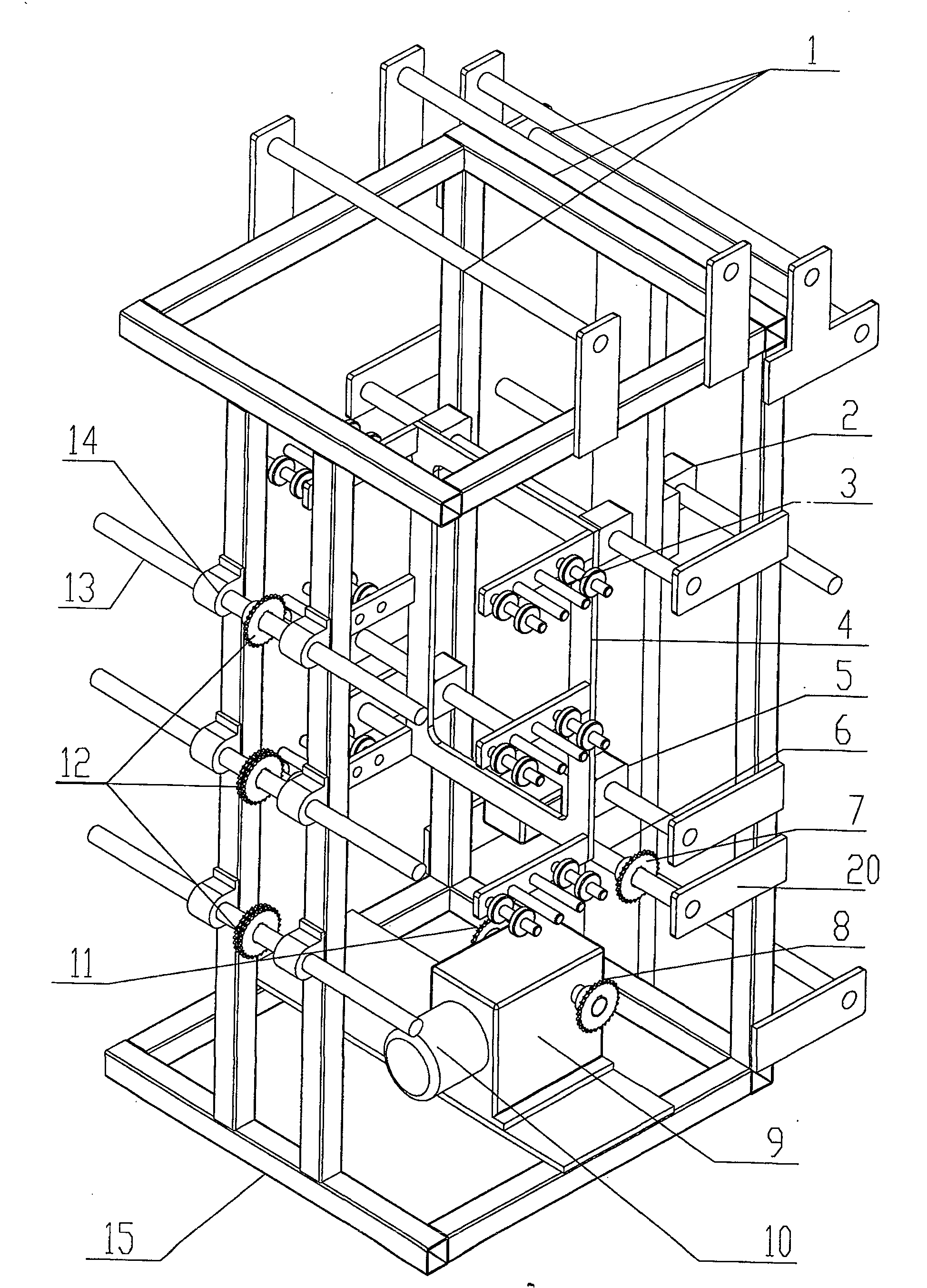
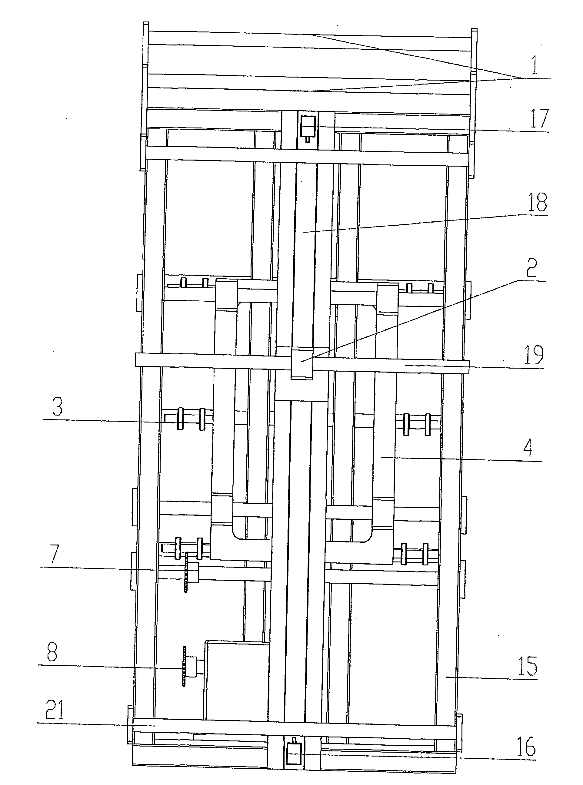

Image

  • Automatic woven tape winding machine
  • Automatic woven tape winding machine

Examples


Embodiment Construction

[0011] The present invention is described in further detail below in conjunction with accompanying drawing:

[0012] like figure 1 , 2 As shown, the main body frame 15 of this invention is welded by 40 square tubes, and three groups of round rods 13 with threads at both ends are installed on the front of the main body frame 15, and the round rods 13 are fixed on the main body frame 15 with bearing blocks 14, The round rod 13 is used to fix the shaft disc skeleton of the winding ribbon. A sprocket 12 is fixed in the middle of the round rod 13. Two sprockets 12 are fixed on the first round rod at the bottom. One is used as a driven wheel and the sprocket 11 passes through the chain. The other is connected as the driving wheel through the chain to the driven wheel on the second round bar 13 on the top of the first round bar 13. In the same way, two sprockets 12 are installed on the second round bar 13, and the uppermost Only a driven wheel is installed on the 3rd round bar 13. ...


PUM


Abstract

The invention discloses a mesh-belt automatic rolling machine which comprises a main body framework, a tension mechanism, a motor, a wire-arrangement device, a winding mechanism and an intermittent winding control device, wherein the tension mechanism is composed of plain shafts and is fixed on the upper surface of the main body framework, the motor is fixed above the main body framework and is connected with a reduction gear box, the wire-arranging device and the winding mechanism are in connection with the reduction gear box via a chain, and the intermittent winding control device is connected with a winding apparatus and the wire-arranging device through the wound mesh belt. The winding mechanism is composed of circular rods and a chain wheel, wherein the two ends of the circular rods are provided with threads, the circular rods are employed to fix the framework of a shaft tray of the mesh belt, and the chain wheel is fixed on the circular rods. The circular rods are fixed on the main body framework via a bearing foundation and are connected with each other via the chain which is hung on the chain wheel, thereby the invention resolves the problem that a plurality of belts outputby a ribbon loom at a time can not be wound synchronously, the investment of labor and material resources is saved, the working efficiency is increased, and the manufacture cost is reduced.

Description

technical field [0001] The invention relates to a textile machine, in particular to an automatic webbing winding machine for webbing. Background technique [0002] At present, whether the tape winding machines on the market are fully automatic or semi-automatic, they can generally only wind a single tape at a time. The machine is driven by a frequency conversion motor through a transmission mechanism to rotate the reel (only a single reel can be placed). The adjustment mechanism and the wire arrangement mechanism are wound on the reel, but for the ribbon equipment that produces multiple ribbons at a time, if this kind of ribbon winding machine is configured, only one ribbon can be wound at a time, and the rest of the ribbons can only be piled up, which cannot meet the requirements. Its production requirements, therefore, a loom needs to be equipped with many winding machines, which not only increases equipment investment, but also may cause the equipment to be idle. Some of ...

Claims


Application Information

Patent Timeline
Patent Type & Authority Patents(China)
IPC IPC(8): B65H18/08B65H23/04D03J1/00D04B37/00
Inventor 封永槐
Owner HEBEI HONGDE PLASTIC HARDWARE PROD
Learn More