Chip-level or symbol-level equalizer structure for multiple transmit and receiver antenna configurations

A technology of transmitting and receiving antennas, applied in the field of code division multiple access receivers, can solve problems such as large implementation complexity, and achieve the effects of suppressing intra-antenna interference, suppressing MAI, and increasing complexity

Inactive Publication Date: 2010-03-03
NOKIA CORP
View PDF2 Cites 0 Cited by
  • Summary
  • Abstract
  • Description
  • Claims
  • Application Information

AI Technical Summary

Problems solved by technology

However, the MAP approximation or maximum likelihood sequence detection (MLSD) method has considerable implementation complexity
The implementation complexity of this MLSD or MAP approximation would be a disadvantage when embedded in a battery powered user terminal with data processor speed and operating power consumption constraints

Method used


Image

  • Chip-level or symbol-level equalizer structure for multiple transmit and receiver antenna configurations
  • Chip-level or symbol-level equalizer structure for multiple transmit and receiver antenna configurations
  • Chip-level or symbol-level equalizer structure for multiple transmit and receiver antenna configurations

Examples


Embodiment Construction

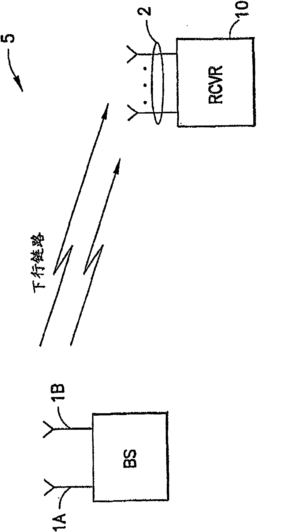
[0018] figure 1 A wireless communication system 5 showing multiple transmit (eg 2) antennas 1A, 1B and multiple receive antennas 2 includes a CDMA receiver 10 suitable for implementing the invention. The receiver may be a user equipment for receiving downlink CDMA signals, eg downlink WCDMA signals, compatible with such as existing or proposed WCDMA 3GPP specifications. The downlink WCDMA can transmit multimedia information to a receiver 10 from the transmitter, which can be a base station with two transmit antennas 1A and 1B.

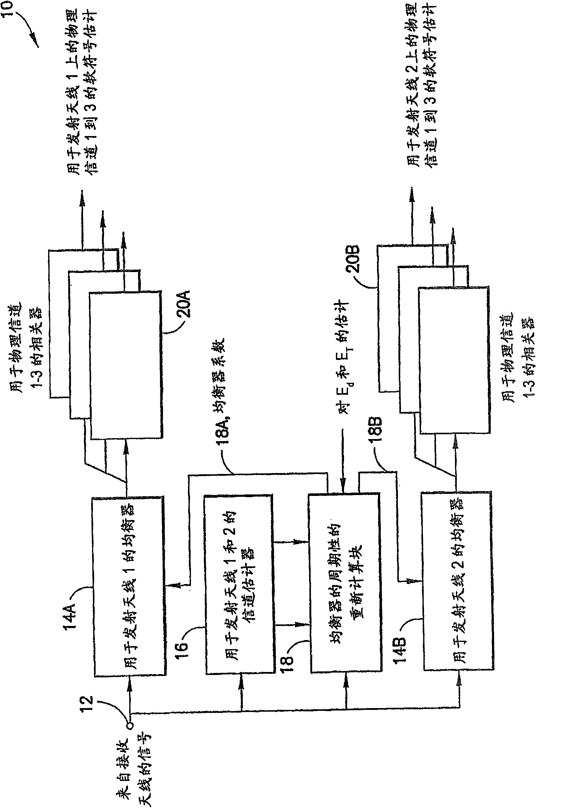
[0019] figure 2 represents a presently preferred embodiment of the CDMA receiver 10 in which the linear channel equalizer (which may be approximated to the LMMSE MUD function) is modified to enhance rejection of inter-antenna interference such that the The suppression of inter-antenna interference and MAI is balanced. Briefly, the CDMA receiver 10 includes a figure 2not shown in ), and an input node 12 for providing the received signal to input ...


PUM


Abstract

Disclosed is chip-level or a symbol-level equalizer structure for a multiple transmit and receiver antenna architecture system that is suitable for use on the WCDMA downlink. The equalizer structure takes into account the difference in the natures of inter-antenna interference and multiple access interference and suppresses both inter-antenna interference and multiple access interference (MAI). Enhanced receiver performance is achieved with a reasonable implementation complexity. The use of the CDMA receiver architecture, in accordance with this invention, enables the realization of increaseddata rates for the end user. The CDMA receiver architecture can also be applied in conjunction with space-time transmit diversity (STTD) system architectures.

Description

technical field [0001] The present invention relates generally to Code Division Multiple Access (CDMA) receivers, and more particularly to CDMA receivers having more than one receiver antenna for use in wireless communication systems having more than one transmit antenna. Background technique [0002] A current trend in modern wireless communication systems is to further increase the transmission data rate to enable the use of multimedia applications (eg, those involving video and / or audio content) by wireless user equipment. For example, in 3GPP (Third Generation, Partnership Project) discussions, the use of multiple transmit and receive antennas has been proposed as a method to increase the data transfer rate. However, it can be appreciated that the use of multiple transmit antennas will inevitably lead to inter-antenna interference where each antenna transmits an independent data stream using the same spreading sequence as the other antennas. This inter-antenna interfere...

Claims


Application Information

Patent Timeline
Patent Type & Authority Patents(China)
IPC IPC(8): H04L25/03H04B7/06H04B1/707H04B1/7115H04J99/00
CPCH04B1/7105H04B2201/709727H04B1/7115H04B7/0891H04L1/0631
Inventor 卡里·奥利凯·基伊斯基拉雅里·伊利奥伊纳斯马克屈·朱恩特蒂
Owner NOKIA CORP
Why Eureka
Try Eureka