Vertical roll of vertical edger and design method thereof

A design method and technology of edger, applied in the direction of roll, metal rolling, metal rolling, etc., can solve the problems of unqualified products, inconsistent width reduction, slits, etc.

Inactive Publication Date: 2010-03-10
BAOSHAN IRON & STEEL CO LTD
View PDF5 Cites 0 Cited by
  • Summary
  • Abstract
  • Description
  • Claims
  • Application Information

AI Technical Summary

Problems solved by technology

However, when rolling a strip billet, when the "dog bone" produced by the lateral pressure deformation in the width direction is rolled by a horizontal roll, slit defects will often be generated on the upper and lower surfaces of the billet, and, due to the There is a distance of 7.89mm between the top of the oblique line in contact with the edge and the vertical line, which makes the width reduction of the upper and lower surfaces of the blank inconsistent, often causing the slit distance on the upper surface to exceed the standard requirement by 4-5mm, resulting in unqualified products , has seriously affected the economic benefits of

Method used


Image

  • Vertical roll of vertical edger and design method thereof
  • Vertical roll of vertical edger and design method thereof
  • Vertical roll of vertical edger and design method thereof

Examples


Embodiment Construction

[0021] The technical solution of the present invention will be further described below in conjunction with the drawings and embodiments.

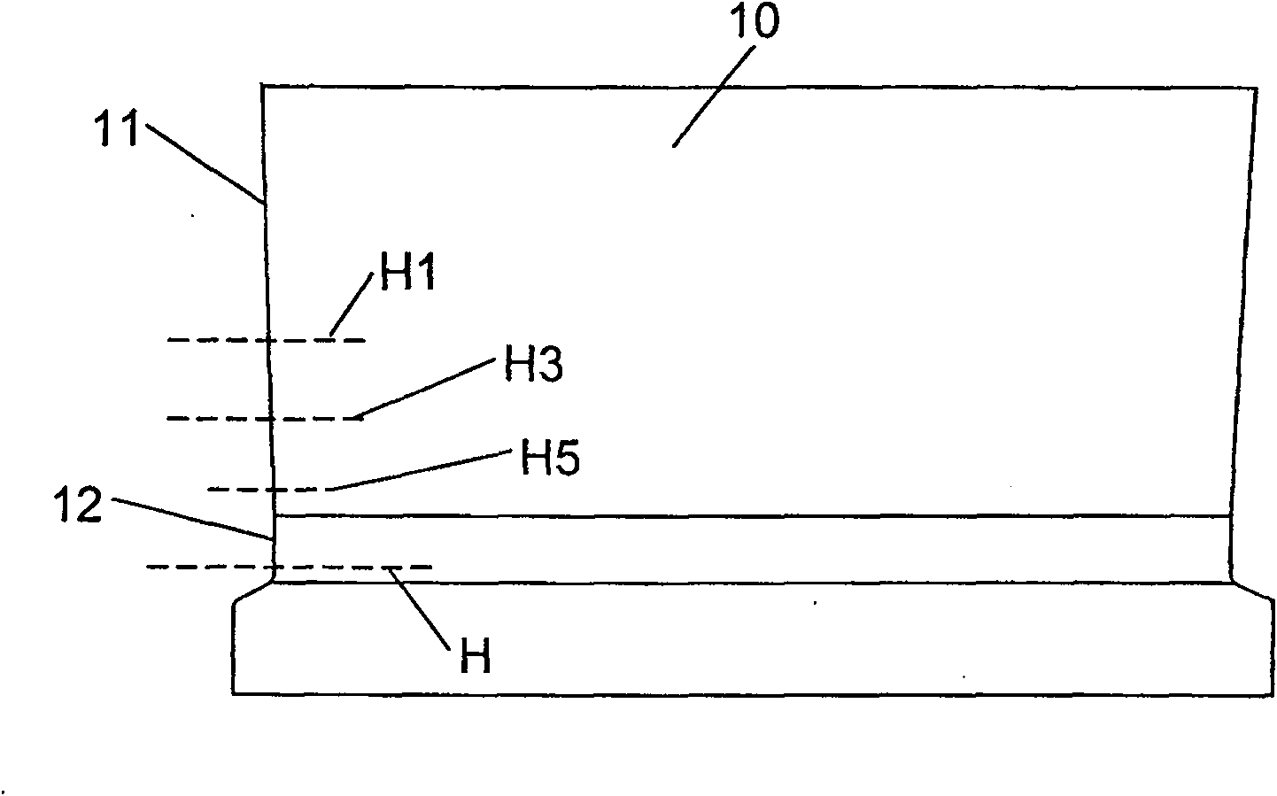
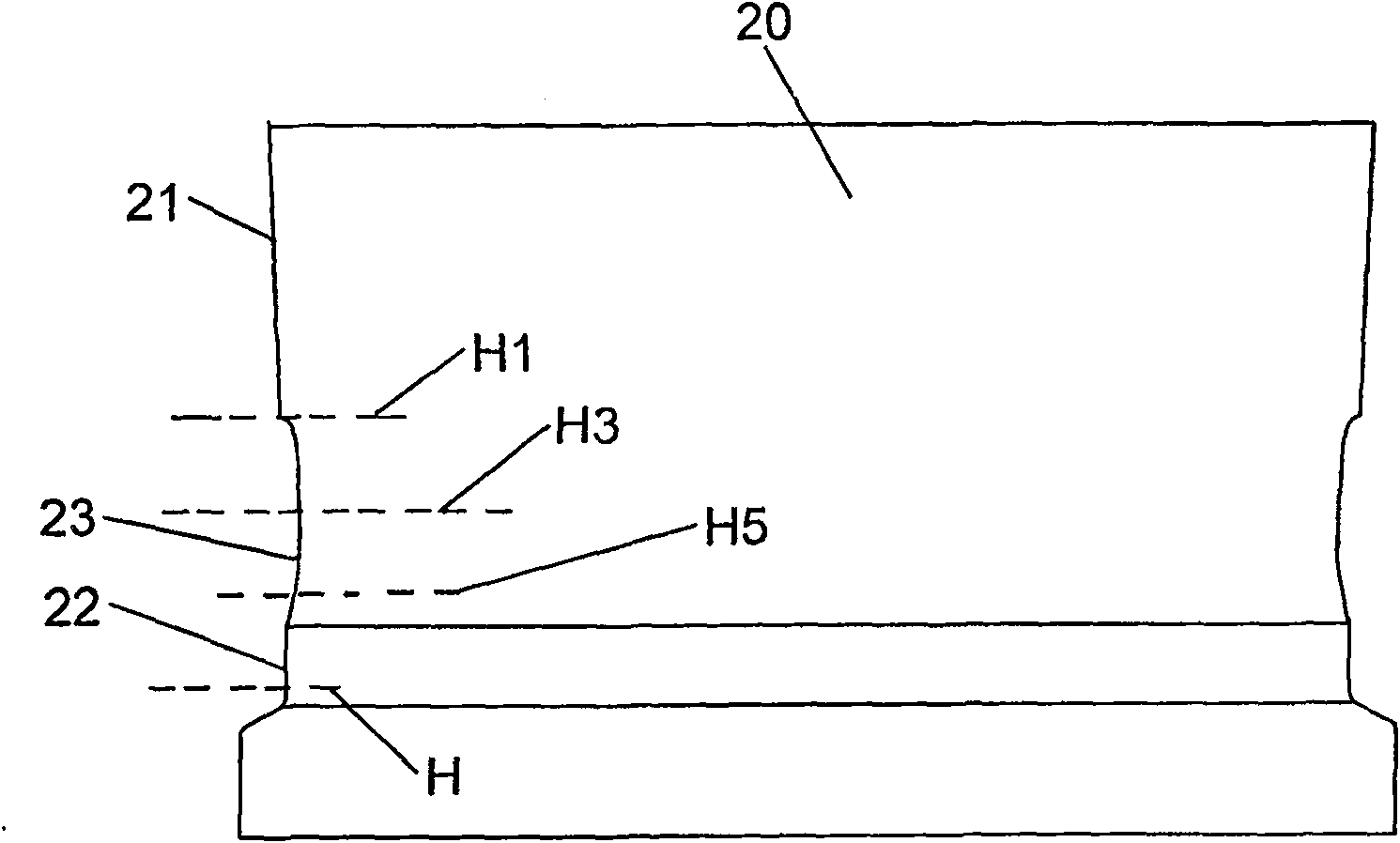
[0022] See image 3 As shown, the two sides of the vertical roll 20 of the vertical roll edging machine of the present invention have a symmetrical structure with the center vertical axis of the vertical roll. Each roll side includes an upper, a middle, and a lower section, and the upper section is a diagonal 21. The lower section is a vertical line 22, and the middle section is an arc line 23 recessed to the inside of the roller. The upper and lower ends of the arc line 23 are respectively connected to the diagonal line 21 and the vertical line 22. The formula of the oblique line 21 in the upper section of the roll side is the same as the oblique line 11 in the prior art (see figure 1 ) Is the same as y=ax, where a=0.05; the middle arc 23 of the roller side is the formula y=ax 2 Parabola 23’ (see Figure 4 ). image 3 Among them, the dashed l...


PUM

PropertyMeasurementUnit
heightaaaaaaaaaa

Abstract

The invention discloses a vertical roller used for a vertical edger; roller edges at the two sides of the vertical roller are symmetric correspondingly to a central vertical shaft of the vertical roller; the roller edges at the two sides comprise three sections: an upper section, a middle section and a lower section; wherein, the upper section is an inclined line, the lower section is a vertical line and the middle section is an arc which is concave towards the internal side of the roller; the upper end and the lower end of the arc are respectively connected with the inclined line and the vertical line. The invention also discloses a design method used for the vertical roller of the vertical edger. By changing the shape of the roller edges at the two sides of the vertical roller, the widthside pressure quantity can be reduced and the requirement of peak value height of dog bone can be reduced; furthermore, in the horizontal direction, the dog bone on the upper surface of the blank wholly generates displacement towards external side so as to cause the width reduction quantity of the upper surface and the lower surface of the blank to be consistent, thus effectively controlling a slot and causing the slot to comply with the standard; furthermore, a side pressure angle is still formed, thus keeping the side pressure capability on the blank and preventing the warping of the blank.The parabola at the middle section of the roller edge is connected with the joint of the inclined line of the upper section and the vertical line of the lower section smoothly, thus preventing the defect that the blank generates the deformation during the rolling process.

Description

Technical field [0001] The present invention relates to a hot rolling mill roll, and more specifically, to a vertical roll of a vertical roll edging machine and a design method thereof. The vertical roll and a design method of the vertical roll can help control the slit of the rolled strip steel. Make it up to standard. Background technique [0002] In the hot strip rolling process, the strip width needs to be controlled. At present, the control equipment for the strip width includes a vertical roll edger, which is characterized by simple equipment and short rolling lines. During rolling, a vertical roll edger and a four-roll reversible roughing mill are used in combination, and the strip blank is rolled on the vertical roll edger for multiple passes, and the width of the blank is adjusted by the odd number of vertical rolls. Process and use the control accuracy of the width model to achieve the target width of rough rolling. See figure 1 As shown, the two sides of the vertical...

Claims


Application Information

Patent Timeline
Patent Type & Authority Patents(China)
IPC IPC(8): B21B27/02
Inventor 邵以诺马文博吴俊侯宝辉罗晶
Owner BAOSHAN IRON & STEEL CO LTD
Why Eureka
Try Eureka