Cleaning device for optical element

A technology for optical components and cleaning fixtures, applied in cleaning methods and tools, cleaning flexible objects, chemical instruments and methods, etc., can solve problems such as difficult fixation, blocking water flow, loss, etc., to improve cleanliness and yield, Easy to put in and take out, control the effect of easy to use

Inactive Publication Date: 2010-07-28
HONG FU JIN PRECISION IND (SHENZHEN) CO LTD +1
View PDF4 Cites 0 Cited by
  • Summary
  • Abstract
  • Description
  • Claims
  • Application Information

AI Technical Summary

Problems solved by technology

First of all, since the V-groove on the side wall of each load rod has a certain thickness and depth, it will block the water flow during use, so that the part of the optical element to be cleaned that is in contact with the V-groove cannot be cleaned, especially when it is to be cleaned The smaller the area of ​​the optical element, the larger the proportion of the part that is in contact with the V-groove
Secondly, the fixed positions of the three bearing rods are not easy to control, and it is easy to cause the clamping of the optical components to be cleaned to be too tight or too loose. Optical components are prone to detachment and loss during cleaning

Method used


Image

  • Cleaning device for optical element
  • Cleaning device for optical element
  • Cleaning device for optical element

Examples


Embodiment 1

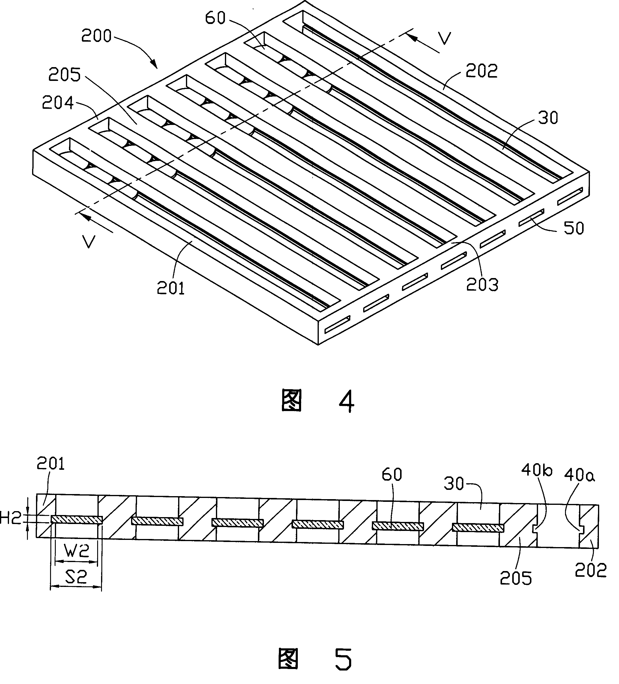
[0026] In the optical element cleaning jig provided in Embodiment 1 and Embodiment 2, the first frame 201, the second frame 202, and the partition 205 are all in the shape of rectangular strips, thereby forming a rectangular strip-shaped cavity 30 for use in It is suitable for cleaning optical components of the same size to be cleaned. Of course, the shape of the accommodating cavity 30 can also be adjusted by changing the shapes of the first frame 201 , the second frame 202 and the partition 205 .

[0027] see Image 6 , is a top view of the optical element cleaning jig 300 provided in the third embodiment. The structure of the optical element cleaning jig 300 is substantially the same as that of the optical element cleaning jig 100 provided in Embodiment 1, which includes a first frame 201 and a second frame 202 opposite to each other, a third frame 203 opposite to a fourth frame 202, and a fourth frame 203 opposite to each other. Border 204 . The difference is that the f...


PUM


Abstract

An optical element cleaning tool is composed of the opposite first and second rims with a pair of slots on their opposite inner surfaces, and the opposite third and fourth rims to form a holding cavity. Said third rim has an opening communicated with said slots.

Description

【Technical field】 [0001] The invention relates to a cleaning jig for cleaning optical elements such as lenses. 【Background technique】 [0002] In optical modules such as cameras, digital cameras, and mobile phone camera lenses, there are more and more types of optical components, including lenses or filters made of glass or plastic. These optical components need to undergo a cleaning process before and after coating to remove dirt, grease, dust particles, etc. attached to the surface of the optical components. Whether the optical components are clean or not will directly affect the quality of their coatings. Therefore, the cleaning of optical components is the key to improving the quality of their coatings. [0003] In the prior art, optical elements are cleaned by fixing the optical elements to be cleaned by means of three-point fixation. For example, the No. 269124 new patent announced by the Intellectual Property Office of Taiwan on July 1, 2005 discloses a cleaning mec...

Claims


Application Information

Patent Timeline
Patent Type & Authority Patents(China)
IPC IPC(8): B08B11/02
Inventor 余泰成李欣和董才士
Owner HONG FU JIN PRECISION IND (SHENZHEN) CO LTD
Why Eureka
Try Eureka