Supercharge Your Innovation With Domain-Expert AI Agents!

Punching shaping technology of bar metal

A stamping forming and bar-shaped metal technology, applied in forming tools, metal processing equipment, manufacturing tools, etc., can solve the problems affecting the quality of the forming surface and increasing the production cost of the product, so as to achieve low production cost, prevent wrinkles and simplify the processing technology Effect

Inactive Publication Date: 2007-07-18
NINGBO XINTAI MACHINERY
View PDF0 Cites 0 Cited by
  • Summary
  • Abstract
  • Description
  • Claims
  • Application Information

AI Technical Summary

Problems solved by technology

Obviously, such a method not only affects the quality of the molding surface, but also increases the production cost of the product.

Method used


Image

  • Punching shaping technology of bar metal
  • Punching shaping technology of bar metal

Examples


Embodiment Construction

[0016] The present invention will be further described in detail below in conjunction with the accompanying drawings and embodiments.

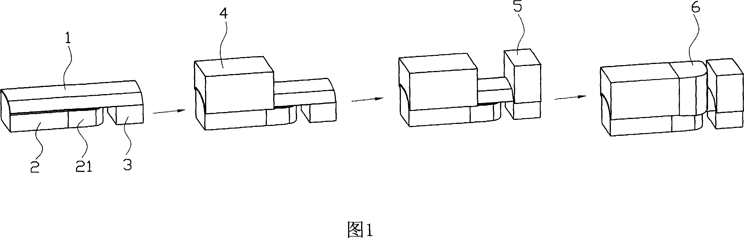
[0017] As shown in Figure 1, the stamping process of the bar-shaped metal adopts the following processing steps: ① place the workpiece 1 to be processed on the front lower module 2 and the rear lower module 3 that are separated from each other, here, the front end of the front lower module Part of the design is in the structure of the punch 21, and the forming area of ​​the workpiece 1 to be processed is directly corresponding to the punch; ②The front upper module 4 corresponding to the front lower module 2 is pressed on the workpiece to be processed on the side of the forming area, that is, pressed against the front The rear end part of the lower module 2, and press the workpiece to be processed on this side, restricting the degree of freedom of the workpiece to be processed on this side, so as to prevent its movement during the forming proces...


PUM

PropertyMeasurementUnit
thicknessaaaaaaaaaa

Abstract

The present invention relates to a press-forming process of strip metal. Said process includes the following steps: (1), placing the workpiece to be machined on the mutually-spaced front and rear lower modules; (2), making the front upper module be tightly pressed on the workpiece positioned in one side of forming zone; (3), making the rear upper module be pressed on the workpiece positioned in another side of forming zone, and applying preload capable of making material be flowed on rear upper module; (4), making ram head female die be quickly downwards moved and pressed on the workpiece to be machined between front and rear upper modules to make it envelope male die so as to form semi-finished product; and (5) utilizing cutting die to cut edge of said semi-finished product and obtain the required product.

Description

technical field [0001] The invention relates to a metal forming processing technology, in particular to a strip metal stamping forming technology. Background technique [0002] At present, in the bar-shaped metal stamping forming process, after calculating the machining allowance and the unfolding of the blank in advance, the material is blanked into the workpiece to be processed, and then the workpiece to be processed is placed on the lower module, and the non-forming area of ​​the workpiece to be processed is clamped and fixed ; Then move the punch of the upper module down quickly, so that the workpiece to be processed is enveloped on the lower module, and finally the required profile is obtained after trimming. However, it is found in practice that since the non-forming area of ​​the workpiece to be processed is clamped tightly, that is to say, the workpiece to be processed cannot move in all directions, so the molding surface of the product made by the above process is a...

Claims


Application Information

Patent Timeline
Patent Type & Authority Applications(China)
IPC IPC(8): B21D22/22B21D22/30B21D37/12
Inventor 郭良辉邱智学
Owner NINGBO XINTAI MACHINERY
Features
  • R&D
  • Intellectual Property
  • Life Sciences
  • Materials
  • Tech Scout
  • Unparalleled Data Quality
  • Higher Quality Content
  • 60% Fewer Hallucinations
Learn More