

Method of pressing bearing on crankshaft
A crankshaft and bearing technology is applied to the field of press-fitting bearings on the crankshaft, which can solve the problems of easy deformation at the crankshaft of the crankshaft and affect the quality of the crankshaft, and achieve the effect of preventing deformation under force and ensuring the quality of press-fitting.
- Summary
- Abstract
- Description
- Claims
- Application Information
AI Technical Summary
Problems solved by technology
Method used
Image

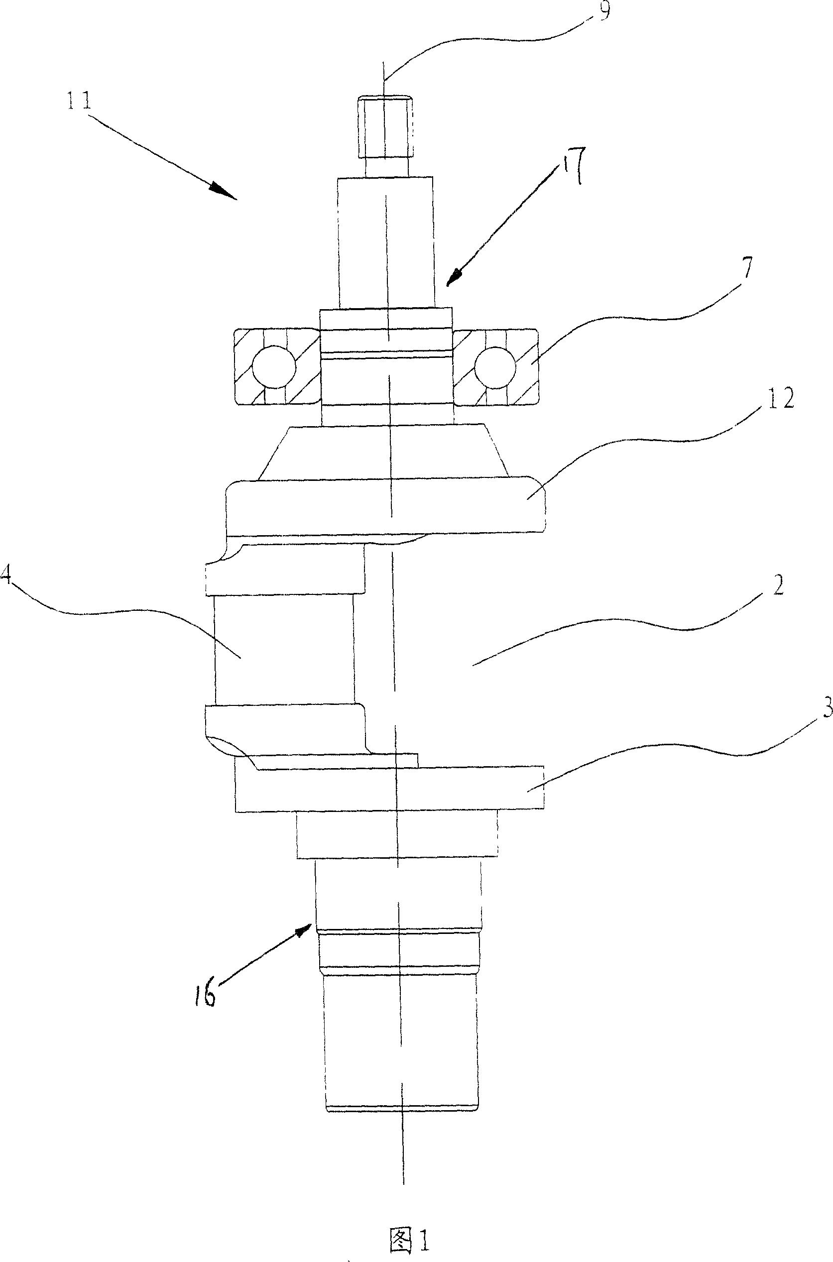
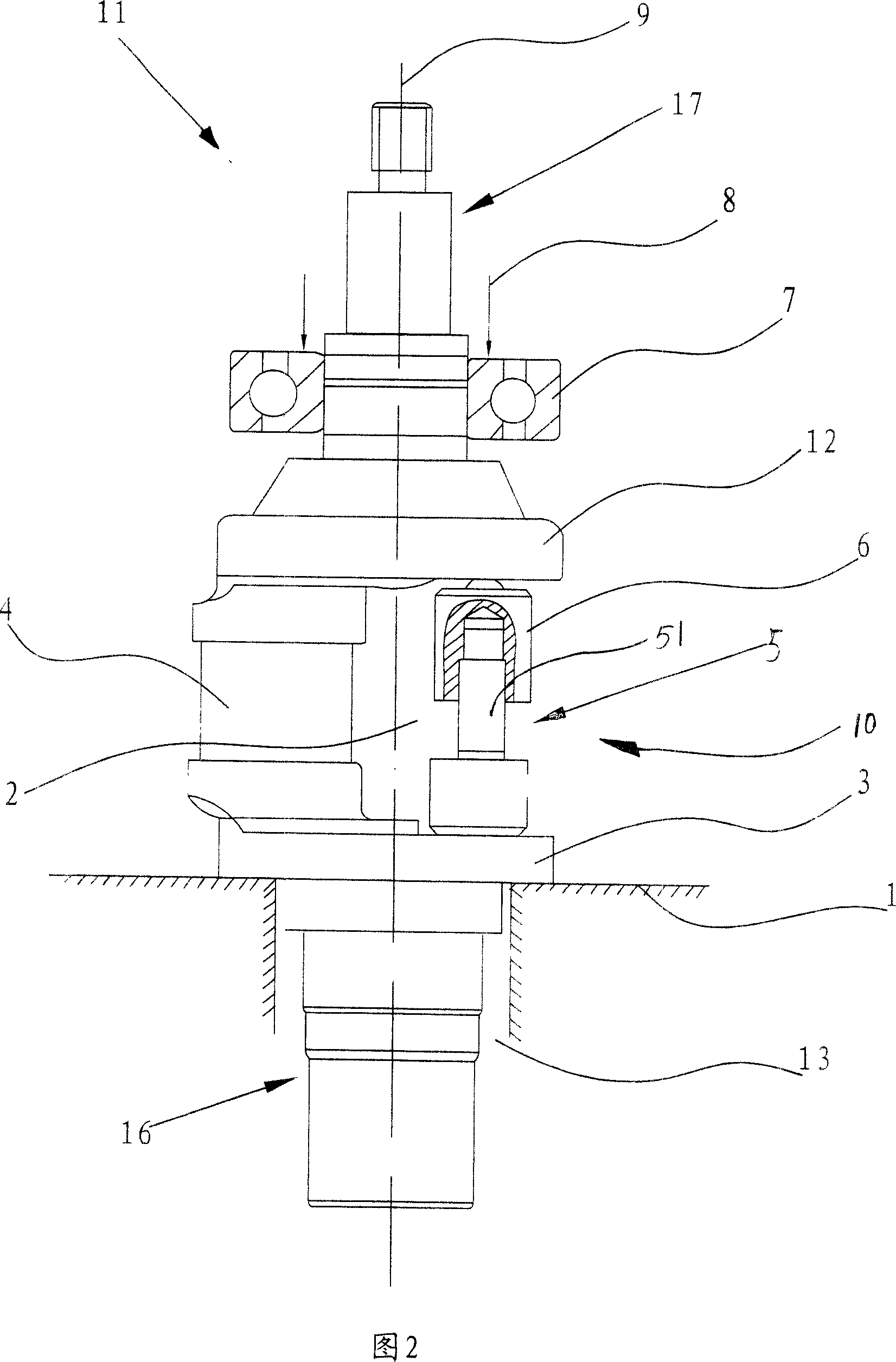
Examples
Embodiment 1
[0022] Accompanying drawing 2 represents the method for installing bearing on crankshaft among the embodiment one, comprises the following steps:
[0023] (a), the crankshaft 11 is fixed on the support frame 1, the support frame 1 is provided with a mounting hole 13, the second main shaft 16 of the crankshaft 11 penetrates into the described mounting hole 13 and makes the The second main journal 3 of the crankshaft 11 is fixedly mounted on the upper mouth of the mounting hole 13;
[0024] (b), the bearing 7 to be installed is sleeved on the upper side of the mounting portion of the crankshaft 11 and the axis line of the bearing 7 coincides with the axis line 9 of the crankshaft 11; The vacant part 2 of the crankshaft 11 is placed along the axis 9 direction of the crankshaft 11. The jack 10 includes a bolt 5 and a screw threaded on the screw 51 of the bolt 5. The cap 6, the bolt 5 is pressed against the upper end surface of the second main journal 3, the nut 6 is pressed again...
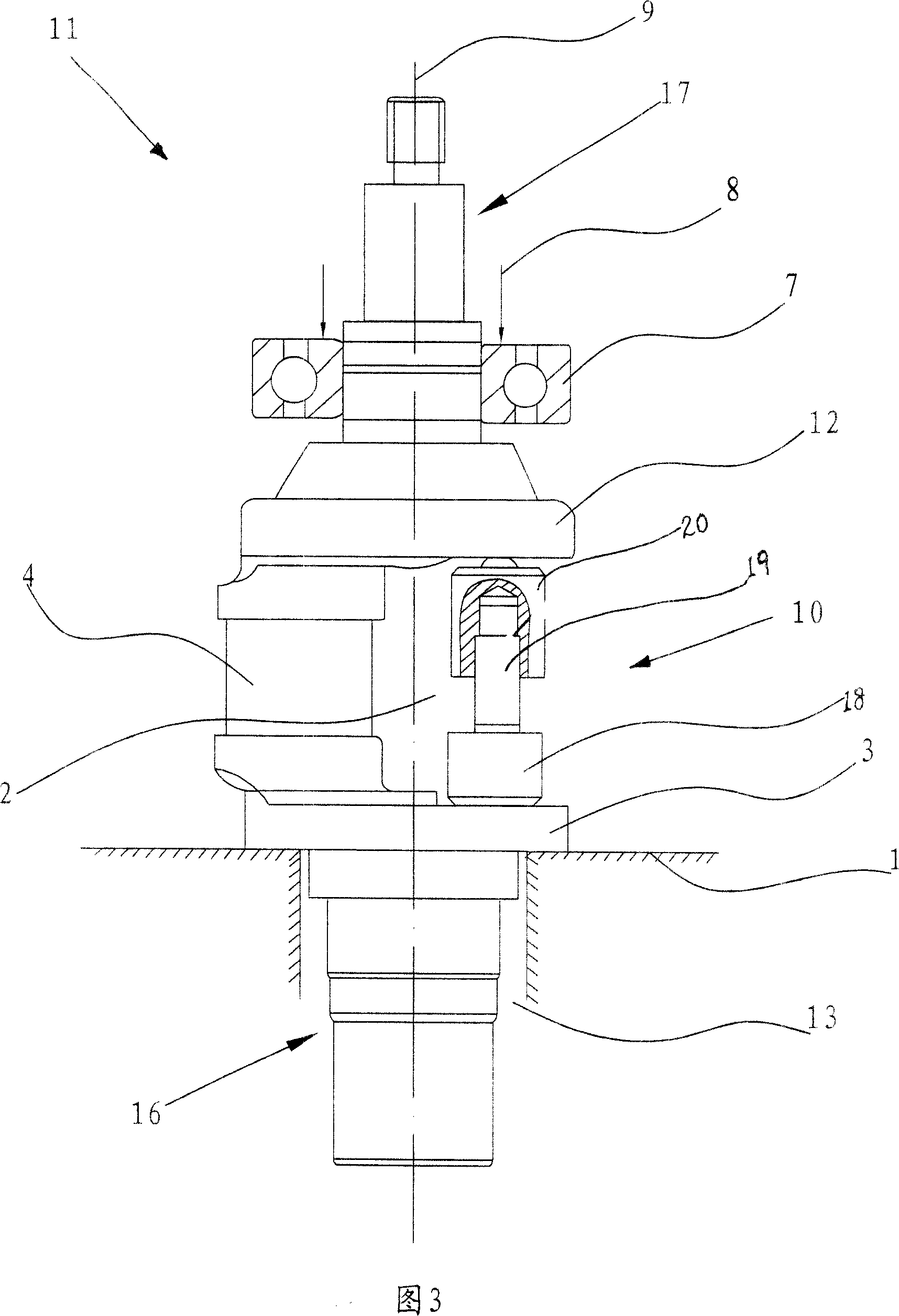
Embodiment 2
[0027] Accompanying drawing 3 represents the method for installing bearing on crankshaft among the embodiment two, comprises the following steps:
[0028] (a), the crankshaft 11 is fixed on the support frame 1, the support frame 1 is provided with a mounting hole 13, the second main shaft 16 of the crankshaft 11 penetrates into the described mounting hole 13 and makes the The second main journal 3 of the crankshaft 11 is fixedly mounted on the upper mouth of the mounting hole 13;
[0029] (b), the bearing 7 to be installed is sleeved on the upper side of the mounting portion of the crankshaft 11 and the axis line of the bearing 7 coincides with the axis line 9 of the crankshaft 11; The vacant part 2 of the crankshaft 11 is placed along the axis 9 direction of the crankshaft 11. The jack 10 includes a lead screw 19 and a nut threaded on the lower end of the lead screw 19. 18. The top cap 20 is fixedly sleeved on the upper end of the screw 19, the top cap 20 is pressed against ...
PUM
 Abstract
Description
Claims
Application Information