Braking device for roller skates

A braking device and roller skate technology, applied to roller skates, ice skating, skateboards, etc., can solve problems such as large demand for technical solutions and no satisfactory solutions found, to eliminate appearance problems, achieve appearance, and reduce damage the dangerous effect of

Inactive Publication Date: 2007-07-18
贝尔特拉姆·布里安 +2
View PDF17 Cites 20 Cited by
  • Summary
  • Abstract
  • Description
  • Claims
  • Application Information

AI Technical Summary

Problems solved by technology

[0010] In short, the fact that the market has a large demand for technical solutions, a large number of patent applications and patents have not yet found a marketable solution shows that, from all aspects, no satisfactory solution has been found so far

Method used


Image

  • Braking device for roller skates
  • Braking device for roller skates
  • Braking device for roller skates

Examples


Embodiment Construction

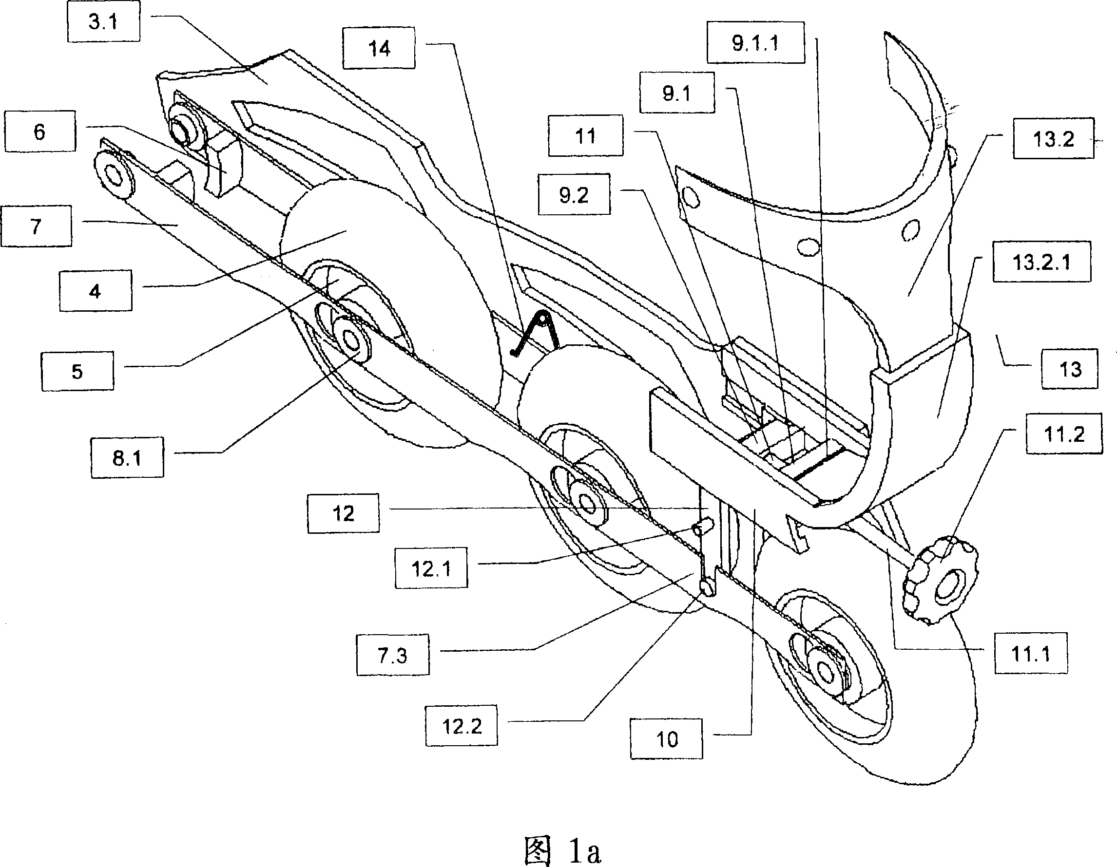
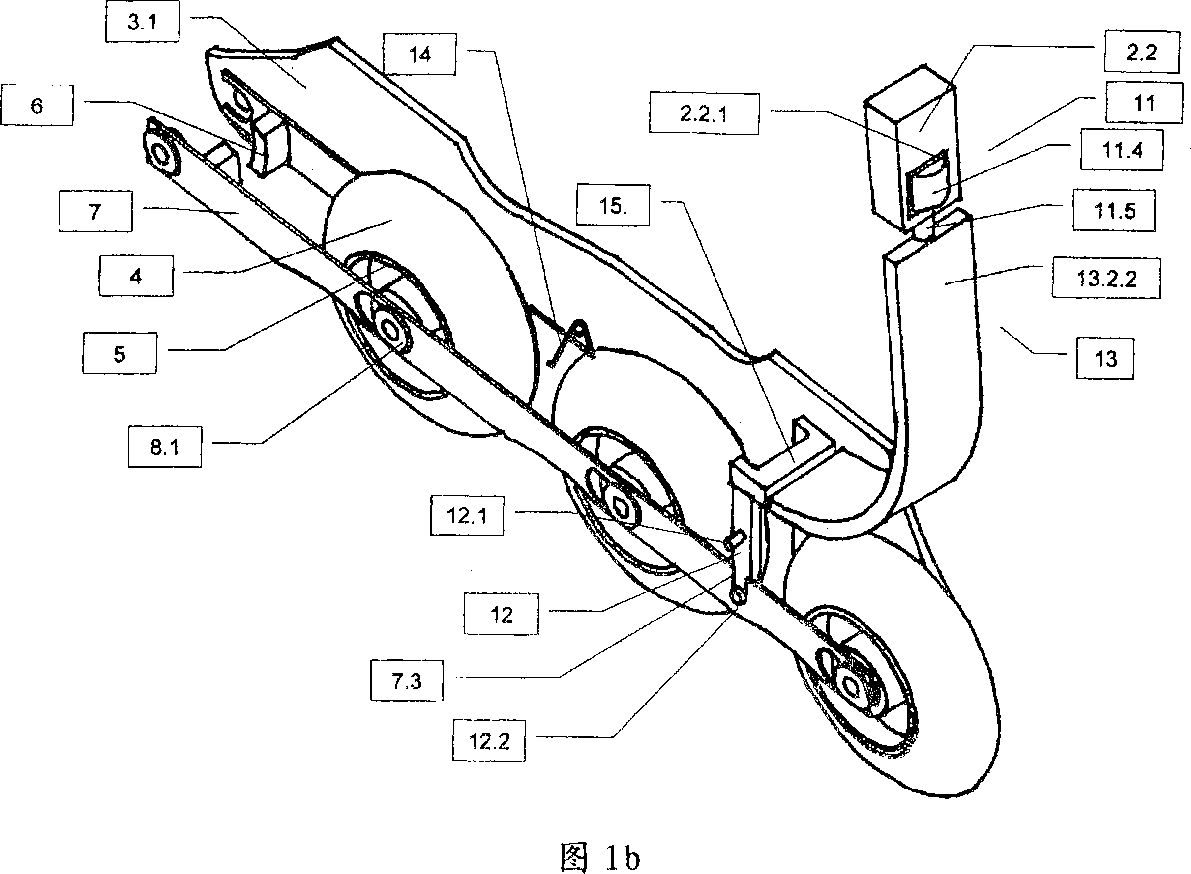
[0061] When the subject group of the present invention is described in detail, the words "front", "rear", "upper", "lower", "vertical" and "longitudinal extension" are firstly defined in detail: here, roller skates or Inline skates are used as a starting point and are used by the user as they glide forward. "Front" refers to the toe cap, "rear" refers to the heel area, "upper", "lower" and "vertical" are observed from the roller skates standing upright on the rollers, and "longitudinal extension" means that the bracket extends longitudinally.

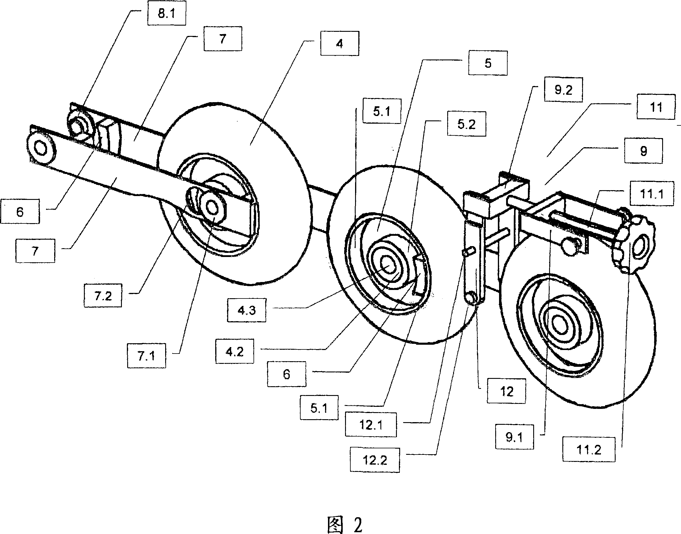
[0062] The roller 4 of the inline skate or roller skate has a rim 5 in which usually two ball bearings 4.2 are inserted, which in turn are mounted on the roller shaft 4.1. In the region of the rim 5 between the ball bearing 4.2 and the starting end of the real roller material, eg polyurethane or rubber, there is enough space to form the brake drum 5. The brake drum is in the form of a cylindrical ring that only penetrates into the rim ...


PUM


Abstract

Disclosed is a braking device for roller skates comprising a shell, a pivotable shaft (2), and a fixture (3) for several rollers (4) that are disposed behind each other in a single row or in two rows. Said rollers (4) are provided with brake drums (5) in which brake shoes (6) can be brought in contact by means of first sliding parts (7) that are actuated via deflection levers (12). Said deflection levers are actuated using second sliding parts (9) that are mounted so as to be adjustable with the aid of an adjusting mechanism (11). The first and / or the second sliding parts are actuated via a transmitting member (13.1 or 13.2) when the shaft (2) is swiveled backwards. The bottom end of the transmitting member (13.2.2) and the second sliding part (9) can be identical. A brake light that is triggered by the braking mechanism is supplied with power via a magnet and a coil.

Description

technical field [0001] The present invention relates to a braking device for roller skates. A combination of three inventions is proposed, which are directly related to each other and jointly realize a general inventive concept. Background technique [0002] The roller skate is composed of a shoe shell, a rotatable boot shaft and a bracket that can be fixed on the sole. The braking device consists of at least one drive link, which can be actuated by the shoe shaft, and at least one first sliding part guided in the region of the support or the sole, which is used to convert the rotational movement of the shoe shaft into a substantially longitudinal direction of the support. Corresponding translation movement. Furthermore, the brake device has at least one brake pad which, when the brake device is actuated, bears against the braking surface of the brake drum located in the roller rim. [0003] As with all running gears, deceleration and braking are equally important issues ...

Claims


Application Information

Patent Timeline
Patent Type & Authority Applications(China)
IPC IPC(8): A63C17/14
Inventor 贝尔特拉姆·布里安彼得·L·利巴利特斯伯恩特·维希哈特
Owner 贝尔特拉姆·布里安
Why Eureka
Try Eureka