Method for solving difficulty of looping tail at steel rolling production-line

A looper and looper technology, applied in the field of metallurgy, can solve problems such as complex logic control programs, and achieve the effects of reducing accident time, improving effective operation efficiency, and increasing production volume

Inactive Publication Date: 2007-07-25
HEBEI IRON AND STEEL
View PDF0 Cites 21 Cited by
  • Summary
  • Abstract
  • Description
  • Claims
  • Application Information

AI Technical Summary

Problems solved by technology

Usually such a method is to use the corresponding delay program to control a certain looper to f

Method used


Image

  • Method for solving difficulty of looping tail at steel rolling production-line
  • Method for solving difficulty of looping tail at steel rolling production-line
  • Method for solving difficulty of looping tail at steel rolling production-line

Examples


Embodiment Construction

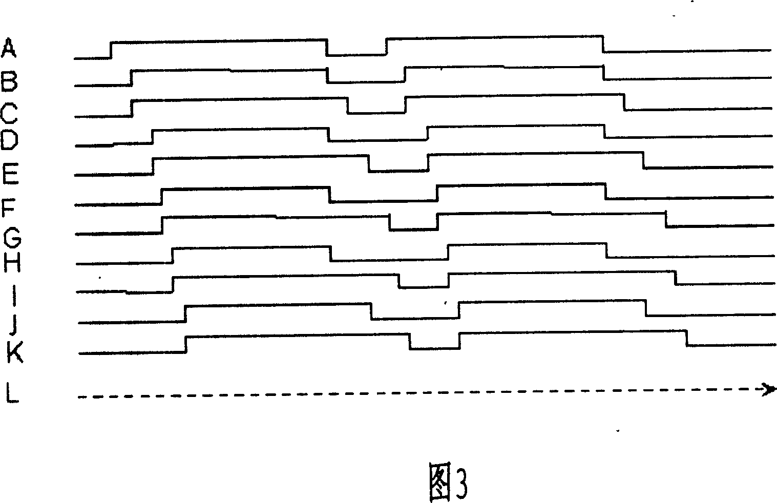
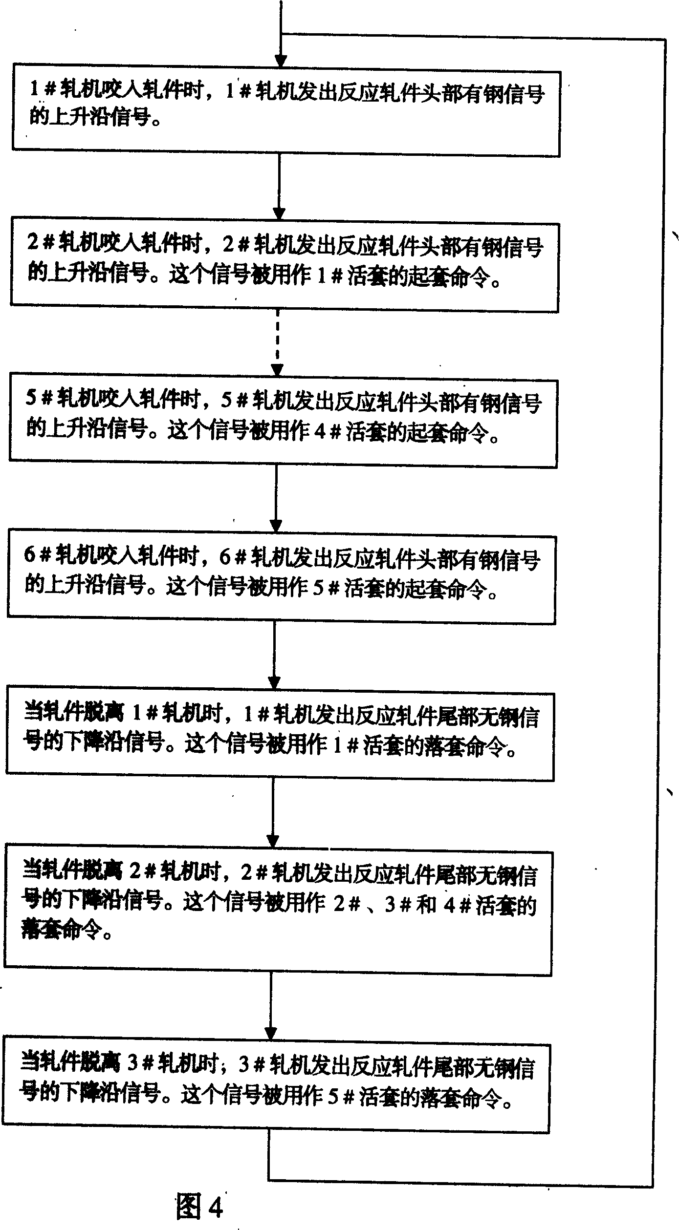
[0020] The invention utilizes the load signal of the upstream rolling mill to control the downstream looper to start the falling action one to three rolling mills ahead of time, thereby effectively solving the problem of looper flicking.

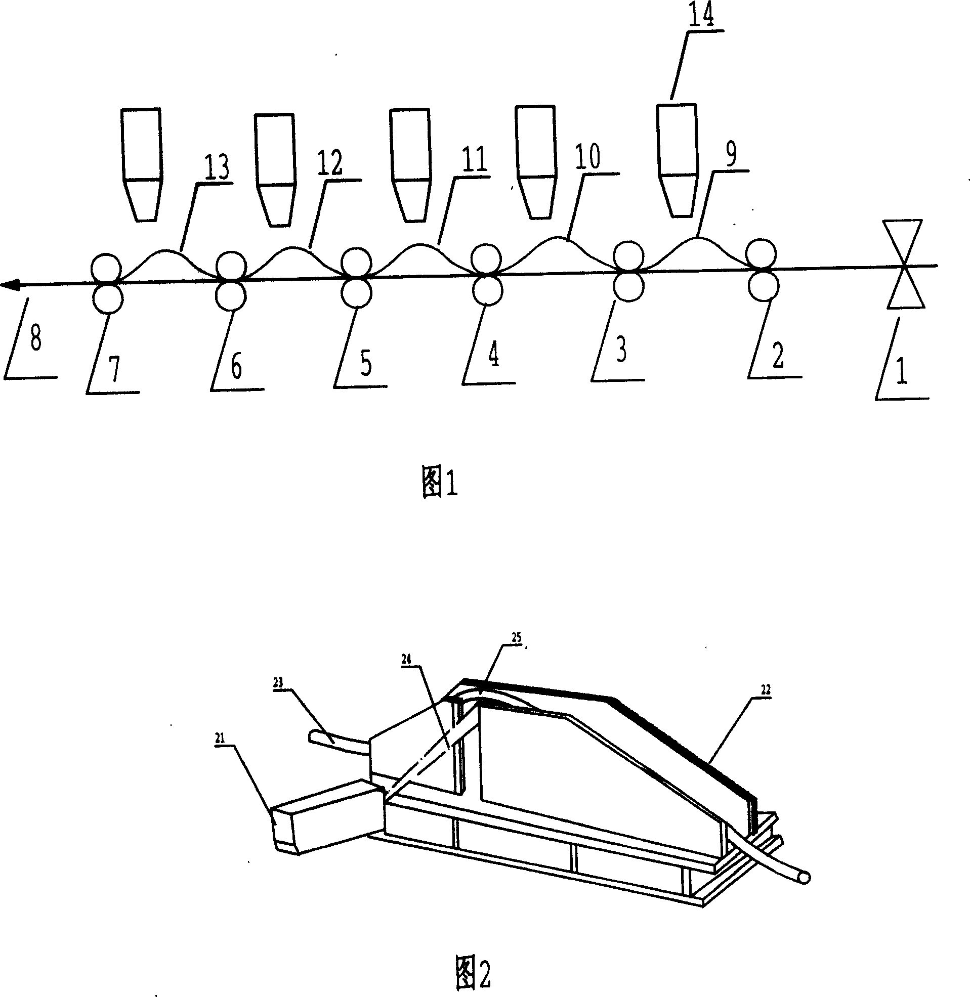
[0021] An embodiment of the present invention is made up of 6 finishing mills and a steel rolling production line with 5 loopers, and a looper is arranged between every two finishing mills, as follows:

[0022] Fig. 1 is a schematic layout diagram of rolling mills and loopers of the finishing rolling train of the steel rolling production line in this embodiment. In the unimproved finishing rolling process, the finishing rolling group has five loopers located between two adjacent rolling mills respectively, and the looping command comes from the load head signal of the downstream rolling mill, that is, in response to the rising edge of the rolling mill load signal. The set-off command comes from the load tail signal of the upstream mill, that...


PUM


Abstract

A method for preventing the loops from not containing the steel tail features that the load head signal of down stream rolling mill is used as the loop lifting command, the load tail signal of upstream rolling mill is used as the loop lowering command, and the load signal of the first rolling mill is directly used as the control signal of the loop lifters for the next three rolling mills.

Description

technical field [0001] The invention relates to a method for controlling loopers in a steel rolling production line, belonging to the technical field of metallurgy. Background technique [0002] Modern small-scale hot rolling production mostly uses vertical loopers, the frame of which is welded, and the looper rolls are driven by cylinders. The cylinder drives the rotating shaft to make the looper roller installed on the looper arm swing up and down, so that the rolled piece forms a looper. The cylinder is installed above the rolling line on the transmission side for easy maintenance and adjustment. The looper inlet and outlet are equipped with upper and lower guide rollers. There are two separate roller tables in the middle, which play the role of transporting the rolled pieces. During the whole rolling process, the rolled piece is bitten by the second finish rolling mill and removed from the sleeve until the tail of the rolled piece falls out of the last finish rolling ...

Claims


Application Information

Patent Timeline
IPC IPC(8): B21B37/72B21B37/00B21B41/00
Inventor 褚建东王春力高峰卢峰马振生刘冬华刘安孙禹王彦生张鑫
Owner HEBEI IRON AND STEEL
Why Eureka
Try Eureka