
Dooly compartment self going type elevator

A self-propelled, car technology, applied in the field of elevators, can solve problems such as inconvenience in use, and achieve the effects of simple application, stable operation and high transportation height

Inactive Publication Date: 2007-07-25
JINAN HEAVY MACHINERY JOINT STOCK
View PDF0 Cites 26 Cited by
  • Summary
  • Abstract
  • Description
  • Claims
  • Application Information

AI Technical Summary

Problems solved by technology

[0002] At present, the power device of the elevator is installed in a certain part of the machine room or the shaft, and the elevator car is driven to reciprocate up and down by the traction rope (wire rope). The application in buildings encounters great difficulties, which are often solved by segmented transportation, causing passengers to change elevators halfway, which is very inconvenient to use

Method used


Image

  • Dooly compartment self going type elevator
  • Dooly compartment self going type elevator

Examples


Embodiment Construction

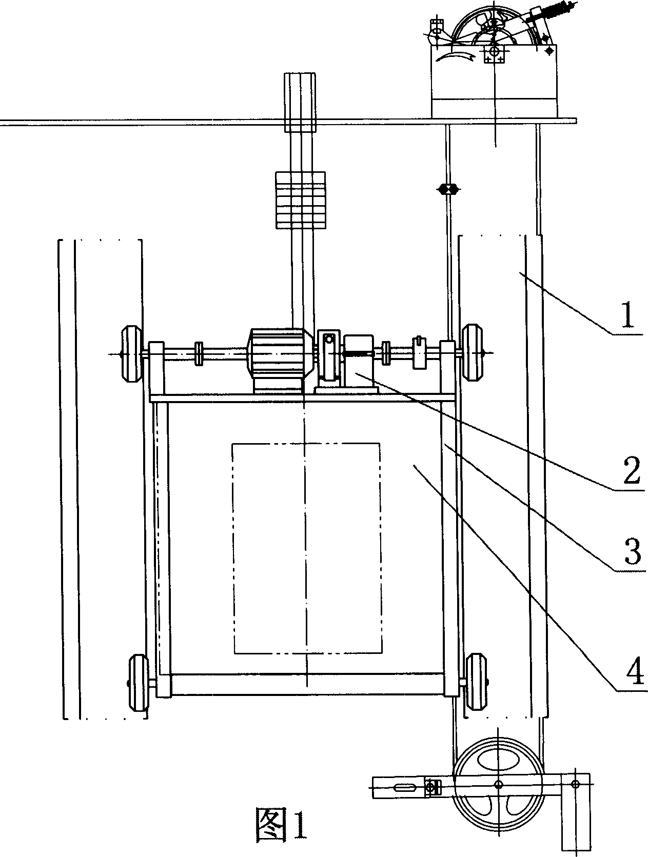
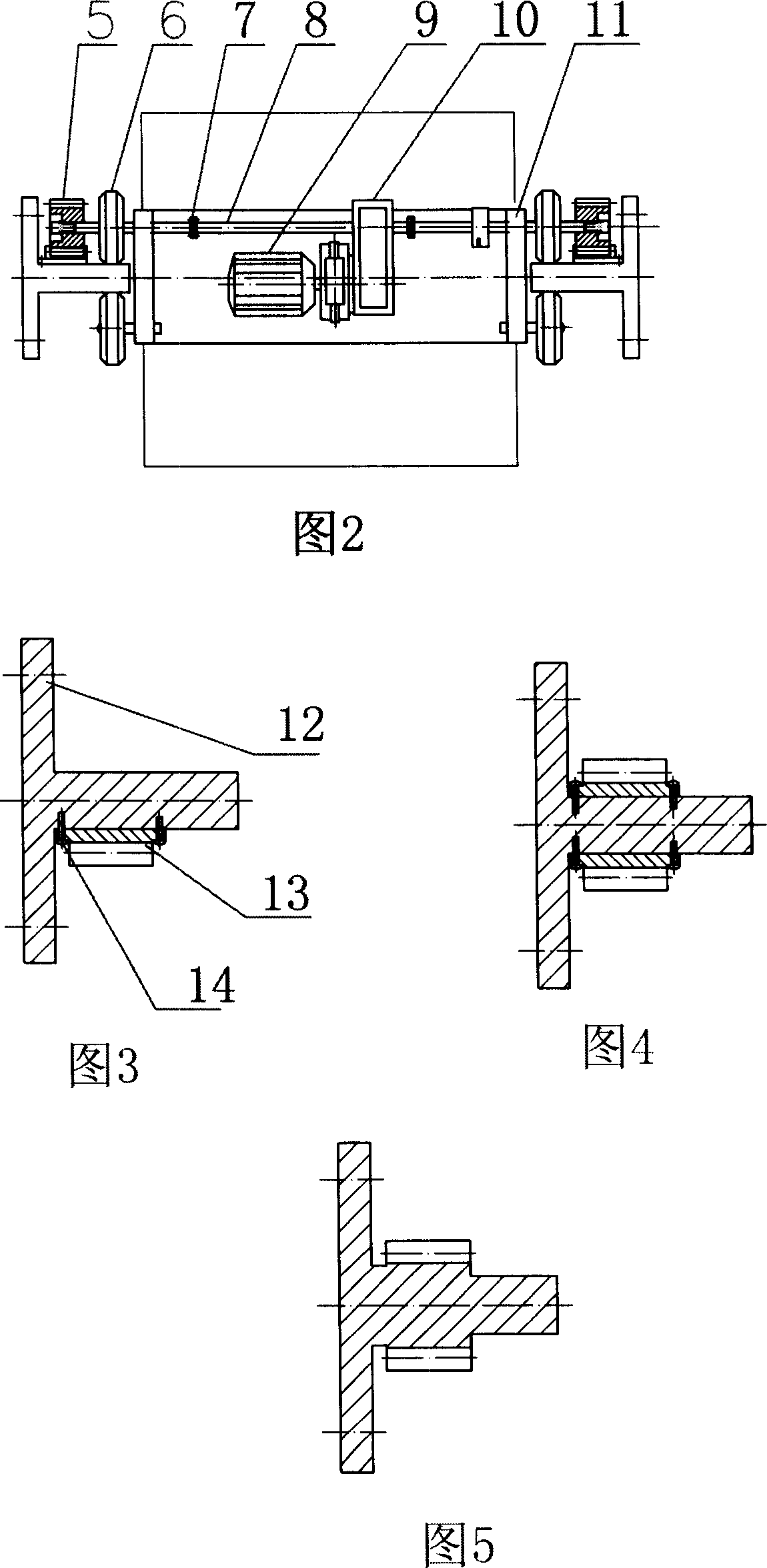
[0010] A kind of specific embodiment shown in Fig. 1, Fig. 2, it comprises elevator shaft and the elevator car that moves up and down in elevator shaft.

[0011] Two rows of elevator guide rails 1 are fixed in the elevator shaft through guide rail brackets, so that the elevator guide rails 1 and the elevator shaft are integrated. As shown in Figure 2, Figure 3 and Figure 4, the elevator guide rail 1 includes a guide rail body 12 and a rack 13. The cross section of the guide rail body 12 is T-shaped, and the installation orientation of the guide rail body 12 in the elevator shaft is the vertical direction of the T-shaped cross section. side towards the middle of the elevator shaft. As shown in Figure 2, one side of the upper vertical edge of the guide rail body 12 T-shaped section is fixed with the rack 13 by a fastener 14, and as shown in Figure 3, the two sides of the upper vertical edge of the guide rail body 12 T-shaped section pass through Fastener 14 is fixing tooth bar ...


PUM


Abstract

An elevator with self-running cage is composed of a shaft with rack bar type track in it, and a cage with a rack-bar-gear engaged self-running mechanism. Its advantage is no need of steel cable.

Description

(1) Technical field [0001] The invention relates to an elevator, in particular to a car self-propelled elevator. (2) Background technology [0002] At present, the power device of the elevator is installed in a certain part of the machine room or the shaft, and the elevator car is driven to reciprocate up and down by the traction rope (wire rope). The application in buildings encounters great difficulties, which are often solved by segmented transportation, which causes passengers to change elevators halfway, which is very inconvenient to use. (3) Contents of the invention [0003] The technical problem to be solved by the present invention is: to provide a self-propelled car elevator, so that the up and down movement of the car does not rely on the traction of the wire rope at all, so that the shortage of the wire rope traction elevator can be overcome, the transportation height is high, and it is suitable for use in high-rise buildings. Or in super high-rise buildings. ...

Claims


Application Information

Patent Timeline
IPC IPC(8): B66B9/02B66B11/04B66B7/02
Inventor 高爱照
Owner JINAN HEAVY MACHINERY JOINT STOCK
Learn More