Pushing press automatic water saving valve

A water-saving valve and push-type technology, which is applied in the field of cut-off devices and push-type automatic water-saving valves, can solve the problems of application field constraints and difficulty in popularization and use, and achieve the effect of stable delay time

Inactive Publication Date: 2007-07-25
吕忠岩 +1
View PDF0 Cites 7 Cited by
  • Summary
  • Abstract
  • Description
  • Claims
  • Application Information

AI Technical Summary

Problems solved by technology

The national standard in this regard can only be delayed for 4-6 seconds, so it is difficult to promote and use it in other occasions, which restricts its application field

Method used


Image

  • Pushing press automatic water saving valve

Examples


Embodiment Construction

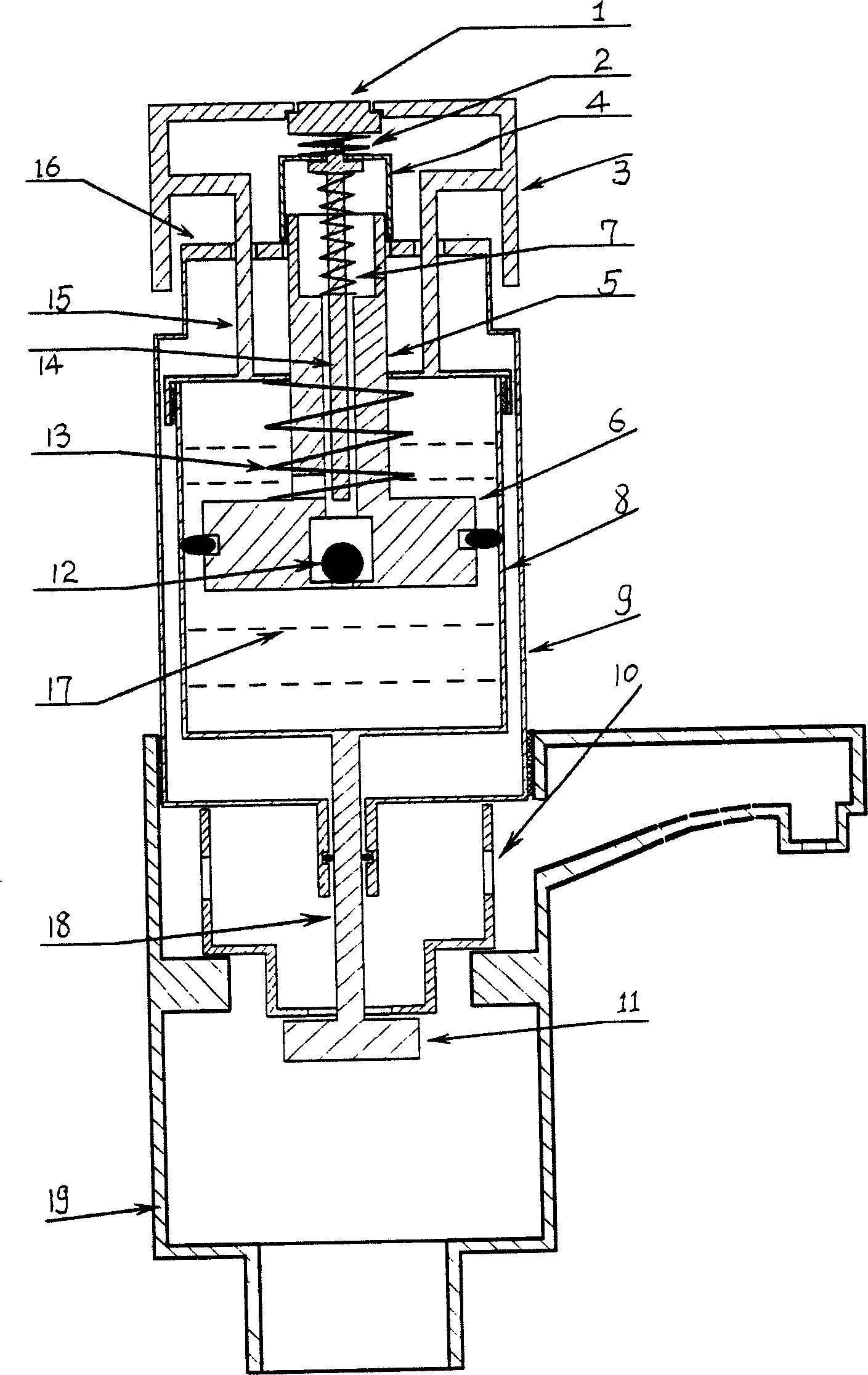
[0009] With reference to accompanying drawing, structure of the present invention is divided into three parts: opening part is made up of opening handle 3, connecting rod 15 oil cylinders 8 valve plates 11. The automatic closing part is made up of closing button 1, button return spring 2, closing push rod 14, piston spring 13, one-way steel ball 12, oil cylinder 8 and oil 17 therein, oil cylinder push rod 18 and valve plate 11. The automatic closing part is made up of piston spring 13, piston 6, one-way steel ball 12, oil cylinder push rod 18 and valve plate 11.

[0010] The push-type automatic water-saving valve of the present invention includes a faucet main body 19, a housing 9 on the main body and an opening handle 3, the opening handle 3 is connected to the oil cylinder 8 through the piston rod 5, the oil cylinder 8 is connected to the oil cylinder push rod 18, and the oil cylinder push rod 18 is connected to the valve. Sheet 11. The piston rod 5 has a built-in valve rod...


PUM


Abstract

The present invention relates to a push-pressing automatic water-saving valve. It includes water tap main body, shell body on the main body and opening handle. Said opening handle is connected with cylinder by means of piston rod, the cylinder push rod is connected with valve plate. In the piston rod interior a valve stem is set, said valve stem is used for closing said control valve, and in the piston a one-way steel ball is set, its piston-fixing nut is fastened in the centre of piston-fixing sheet, and is used for fixing piston.

Description

technical field [0001] The invention relates to a valve structure, in particular to a push-type automatic water-saving valve, which belongs to the technical field of international patent classification F16K1 / 00 "lift valve, cut-off device with closing element". Background technique [0002] Although the old-fashioned push-type water taps in the prior art are convenient to use, their practicability is limited. Because it generally only has the function of opening, but not the function of manual closing, it has to be used in the bathroom. The national standard in this regard can only be delayed for 4-6 seconds, so it is difficult to promote and use it in other occasions, which restricts its application field. Contents of the invention [0003] The object of the present invention is to overcome the deficiencies in the prior art and provide an innovative push-type automatic water-saving valve. [0004] The purpose of the present invention is achieved through the following te...

Claims


Application Information

Patent Timeline
Patent Type & Authority Applications(China)
IPC IPC(8): F16K1/00F16K31/122
Inventor 吕忠岩王建光
Owner 吕忠岩
Why Eureka
Try Eureka