Long delay circuit
A delay circuit and circuit technology, applied in the direction of single output arrangement, etc., can solve the problems of delay time difference, user inconvenience, etc., and achieve the effect of overcoming delay time difference
- Summary
- Abstract
- Description
- Claims
- Application Information
AI Technical Summary
Problems solved by technology
Method used
Image
Examples
Embodiment Construction
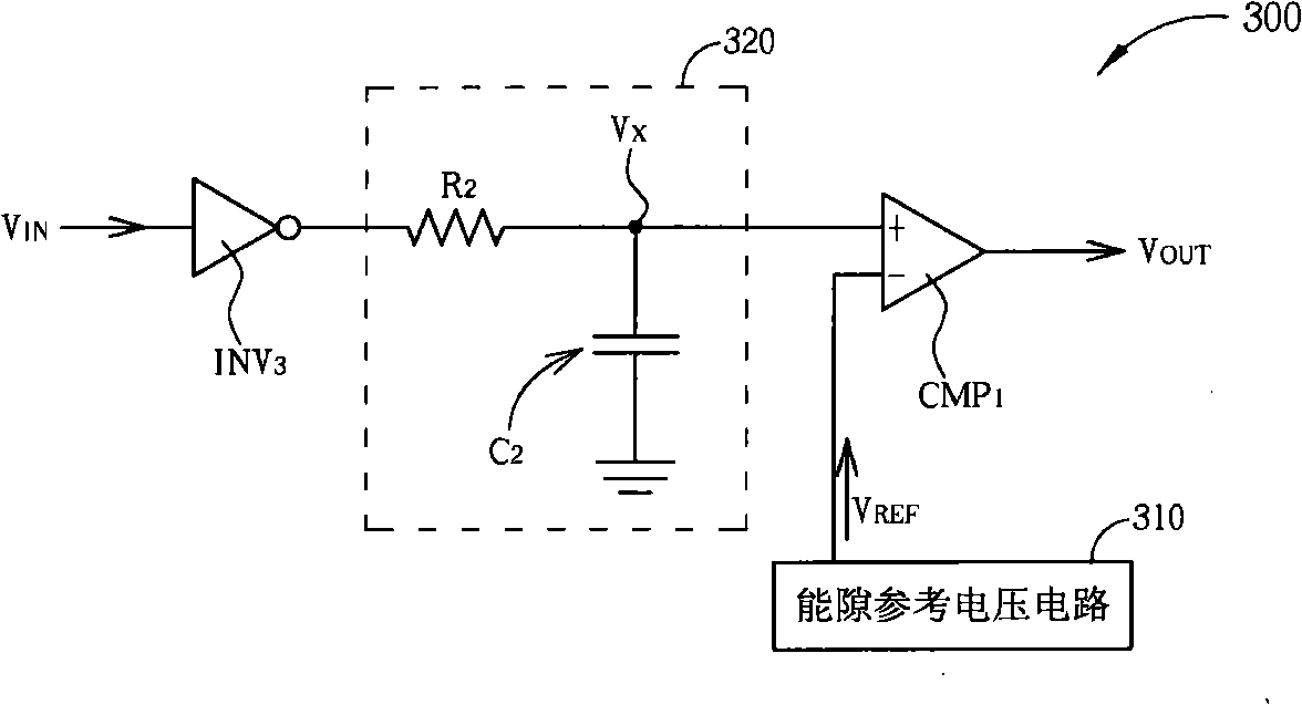
[0020] Please refer to image 3 , image 3 is a schematic diagram of the long-time delay circuit 300 according to the first embodiment of the present invention. The long-time delay circuit 300 includes a delay signal input end, a delay signal output end, an inverter INV 3 , comparator CMP 1 , a bandgap voltage reference circuit (bandgap voltage reference circuit) 310 and a passive component conversion circuit 320 . The passive component conversion circuit 320 can be formed by a combination of resistors and capacitors, that is, the passive component conversion circuit 320 can be implemented as a resistor-capacitor delay circuit.
[0021] The delay signal input terminal of the long-time delay circuit 300 is used to receive the input signal V IN , its delayed signal output terminal is used to output the delayed signal V OUT .
[0022] Inverter INV 3 The input terminal of is coupled to the delay signal input terminal of the long-time delay circuit 300 to receive the input s...
PUM
 Abstract
Description
Claims
Application Information
 - R&D
- Intellectual Property
- Life Sciences
- Materials
- Tech Scout
- Unparalleled Data Quality
- Higher Quality Content
- 60% Fewer Hallucinations
Browse by: Latest US Patents, China's latest patents, Technical Efficacy Thesaurus, Application Domain, Technology Topic, Popular Technical Reports.
© 2025 PatSnap. All rights reserved.Legal|Privacy policy|Modern Slavery Act Transparency Statement|Sitemap|About US| Contact US: help@patsnap.com


