
Omnibearing vision sensor with no dead angle

A technology of omni-directional vision and visual sensor, applied in the field of omni-directional vision sensor without dead angle, can solve problems such as inability to use information

Inactive Publication Date: 2007-07-25
汤一平
View PDF2 Cites 39 Cited by
  • Summary
  • Abstract
  • Description
  • Claims
  • Application Information

AI Technical Summary

Problems solved by technology

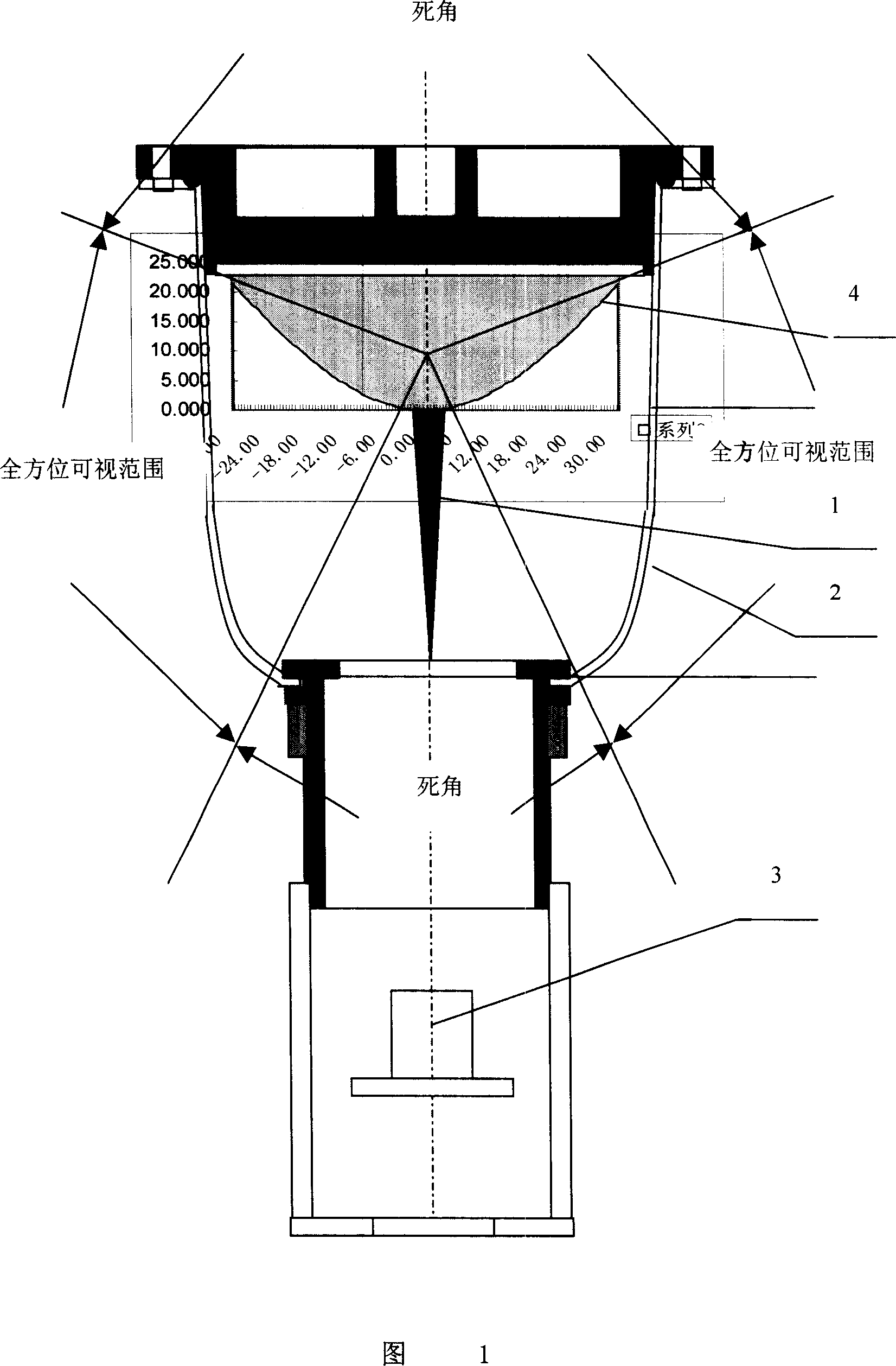
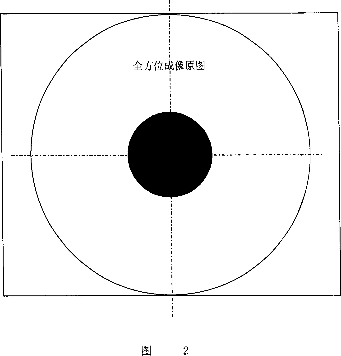
The disadvantages are: the transparent cover has reflected interference light; the black circle in the center is the dead angle of ODVS, and there is a dead angle in the vertical direction, so the information of this part cannot be used

Method used


Image

  • Omnibearing vision sensor with no dead angle
  • Omnibearing vision sensor with no dead angle
  • Omnibearing vision sensor with no dead angle

Examples


Embodiment Construction

[0064] The present invention will be further described below in conjunction with the accompanying drawings.

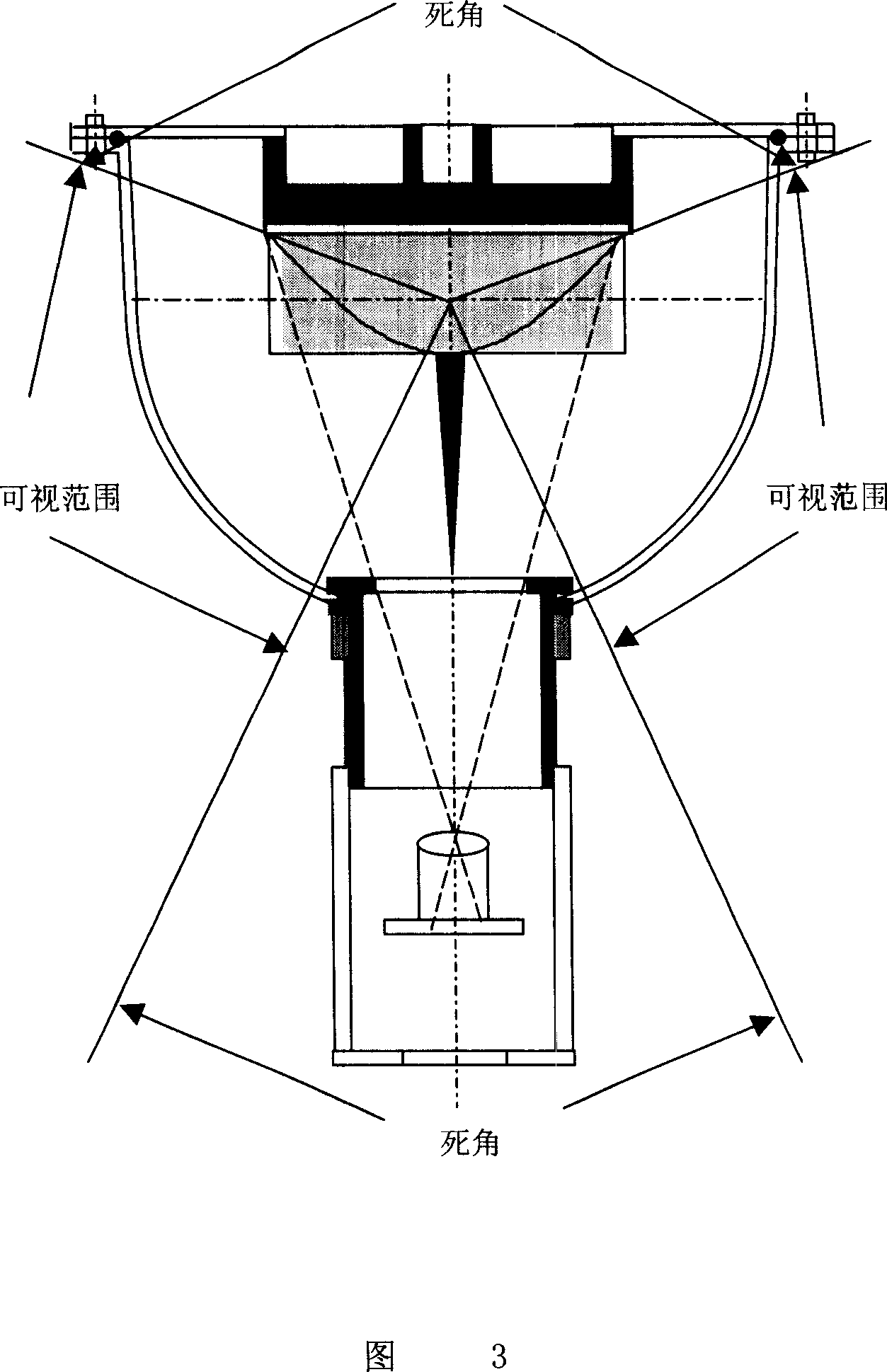
[0065] Referring to Figures 1 to 9, an omnidirectional visual sensor without dead angles includes a bracket 7, a vertically hanging catadioptric mirror 4, a transparent cover 2, and a camera 3, and the catadioptric mirror 4 is located on the top of the transparent cover 2 , the central opening at the bottom of the transparent cover 2, the transparent cover 2 is installed on the bracket 7, the camera 3 is located at the focal point of the catadioptric mirror 4, the catadioptric mirror 4, the transparent cover 2 , the camera 3 is located on the same axis, and the output of the camera 3 is connected to a microprocessor for image processing; the transparent cover 2 is bowl-shaped, and the transparent cover 2 includes a cone on the top and a hemisphere on the bottom. The radius of the hemisphere is in transition with the cone, the center of the hemisphere coincides with the...


PUM


Abstract

An omnibearing visual transducer of blind angle free type is prepared for setting catadioptric lens at top of transparent external cover, arranging an opening at bottom center of said external cover, setting said transparent external cover on support frame, arranging video camera head on focus point of catadioptric lens and setting said catadioptric lens and transparent external cover as well as video camera head to be on the same axle coaxially.

Description

(1) Technical field [0001] The invention belongs to the application of optical technology, computer image processing technology and network communication technology in the field of remote monitoring. It is mainly suitable for intelligent transportation, video fire detection, and elevator safety protection, and is also suitable for monitoring Monitoring, anti-theft monitoring of supermarkets and stores, etc.), video conferencing, mobile phone camera, introduction of city scenery and scenic spots, distance education, automatic navigation and positioning, and medical and other global video information acquisition fields, especially an all-round visual sensor. (2) Background technology [0002] Most imaging systems in use today consist of a video camera (or still camera) and a lens. The projection imaging model of most lenses is the perspective of a single projection center. Because of the limited size of the imaging device (such as a CCD array) and the blocking around the lens...

Claims


Application Information

Patent Timeline
Patent Type & Authority Applications(China)
IPC IPC(8): G03B17/48G02B17/08H04N5/225G06T1/00G03B37/00
Inventor 汤一平
Owner 汤一平
Learn More