Antenna apparatus

An antenna device and technology of each antenna, applied in the directions of antenna, antenna parts, radiating element structure, etc., can solve the problems of communication failure, radio wave receiving sensitivity decline, and large box area.

Inactive Publication Date: 2007-07-25
AUDIO-TECHNICA
View PDF1 Cites 17 Cited by
  • Summary
  • Abstract
  • Description
  • Claims
  • Application Information

AI Technical Summary

Problems solved by technology

[0005] However, because it is planar, the area of ​​the box subject to the wind is large, so the direction of the antenna will change when it is subjected to strong wind
Because the directivity of the Yagi antenna is strong, when the direction of the antenna changes, the receiving sensitivity of the radio wave decreases, which often causes communication failures

Method used


Image

  • Antenna apparatus
  • Antenna apparatus
  • Antenna apparatus

Examples


Embodiment Construction

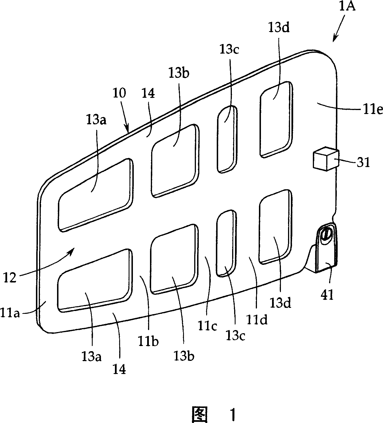
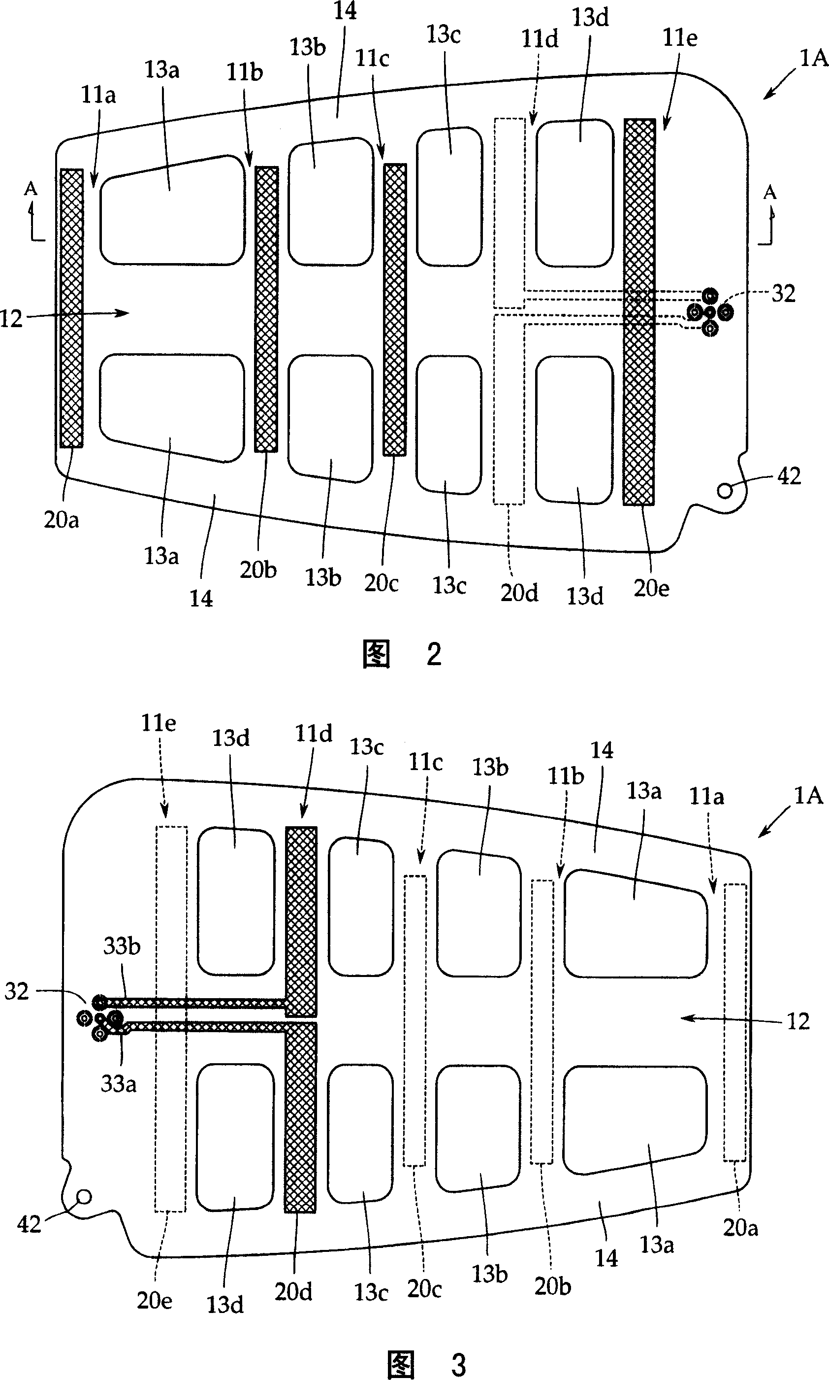
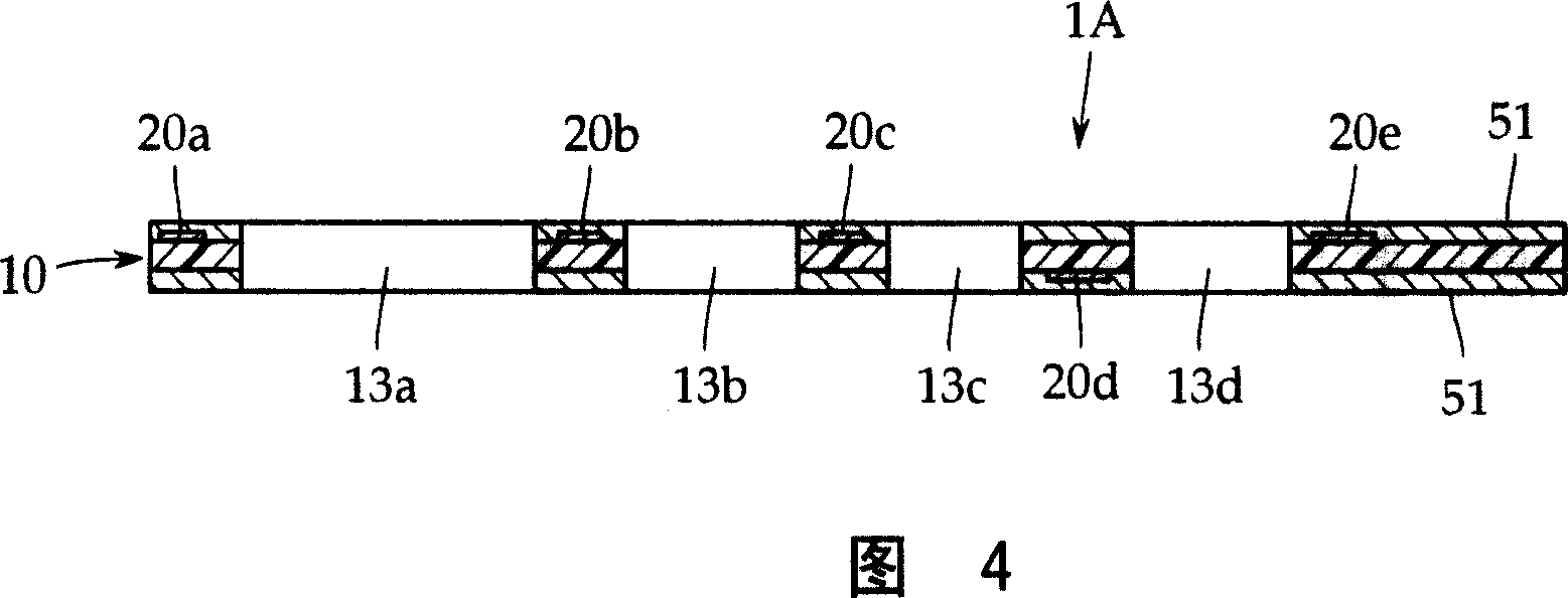
[0024] Several embodiments of the present invention will be described below with reference to FIGS. 1 to 6 , but the present invention is not limited thereto. 1 is an external perspective view showing an example of the antenna device according to the present invention, FIG. 2 is a plan view showing the configuration of one side of the antenna device, and FIG. 3 is a plan view showing the configuration of the other side of the antenna device. As for the plan view, FIG. 4 is a cross-sectional view along line A-A of FIG. 2 , and FIGS. 5 and 6 are plan views showing other embodiments, respectively.

[0025] First, an antenna device 1A according to a first embodiment of the present invention will be described with reference to FIGS. 1 to 4 . This antenna device 1A is a planar Yagi antenna in which a director, an emitter, and a reflector as antenna elements are formed on a dielectric substrate 10, and five antenna elements are used in this example.

[0026] That is, on the dielectr...


PUM


Abstract

The present invention provides a flat antenna apparatus which will not easily suffer wind pressure, has light weight, beautiful appearance and good feed voltage characteristic and is especially adapted to wireless microphone. The antenna apparatus (1A) is formed by mounting a yagi-uda antenna including various antenna elements (20) such as directors (20a-20c), an emitter (20d) and a reflector (20e) on a dielectric substrate (10) made of rigid materials. The various antenna elements (20 (20a-20e)) form various central parts of multiple parallel element forming parts (11 (11a-11e)) that are linked together by a main frame plate (12) in prescribed space, and form space parts (13 (13a-13d)) among the elements forming parts (11 (11a-11e)).

Description

technical field [0001] The present invention relates to an antenna device formed by forming a Yagi antenna (Yagi antenna) on a dielectric substrate. Specifically, it mainly relates to an antenna device suitable for use as a receiving antenna for a wireless microphone used indoors or outdoors on stages or recording studios, etc. Antenna device. Background technique [0002] The present invention relates to an antenna device formed by forming a Yagi antenna on a dielectric substrate. Specifically, the present invention mainly relates to an antenna device suitable for use as a receiving antenna for a wireless microphone used on indoor or outdoor stages or recording studios. [0003] A typical Yagi antenna is made by arranging the antenna elements (antenna elements) of the director, emitter, and reflector made of metal rods in parallel with each other at predetermined intervals. However, in recent years, the dielectric substrate A planar Yagi antenna in which antenna elements a...

Claims


Application Information

Patent Timeline
Patent Type & Authority Applications(China)
IPC IPC(8): H01Q1/38H01Q19/30
CPCH01Q1/005H01Q1/241H01Q1/38H01Q1/40H01Q19/30
Inventor 浜冈辉雄小诸浩和
Owner AUDIO-TECHNICA
Why Eureka
Try Eureka