
Electrical conductor cable and method for forming the same

A technology of electrical conductors and cables, applied in the field of electrical conductors and cables and their formation, can solve problems such as difficult coiling, and achieve the effects of suppressing influence, reliable joints, and low cost

Inactive Publication Date: 2007-07-25
GIFT TECH LP
View PDF1 Cites 3 Cited by
  • Summary
  • Abstract
  • Description
  • Claims
  • Application Information

AI Technical Summary

Problems solved by technology

However, a core member exhibiting sufficient rigidity to withstand the loads of the cable would make it difficult to coil

Method used


Image

  • Electrical conductor cable and method for forming the same

Examples


Embodiment Construction

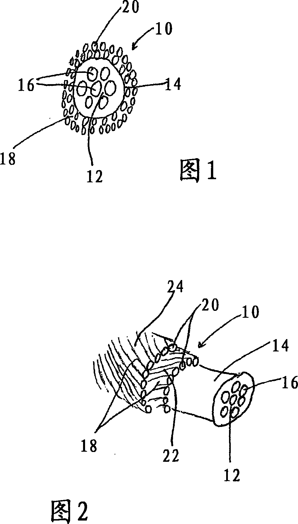
[0039] The present invention teaches an electrical conductor cable and a method of forming the same, wherein in said electrical conductor cable the central support core comprises a plurality of individual non-conductive cylindrical core parts, electrically conductive The components are located on the exterior surface of the core.

[0040] Figure 1 shows an end view of an exemplary embodiment of the invention. An electrical conductor cable 10 is shown. The electrical conductor cable 10 includes a core 12 having an outer sheath 14 and a core member 16 . The cable 10 also includes a conductive outer surface 18 that overlies the sheath 14 of the core 12 .

[0041] Core component 16 of core 12 may be formed from a reinforced plastic composite, carbon fiber composite, or glass composite, or any combination thereof. The material used to form core member 16 may be impregnated with resin and cured by any known method, including curing during a pultrusion process or by ultraviolet li...


PUM

PropertyMeasurementUnit
diameteraaaaaaaaaa

Abstract

An electrical conductor came for long distance transmission of electrical current is provided. The conductor came includes a plurality of individual cylindrically shaped non-conductive components. The conductor cable further includes an electrically conductive m tuber located on an exterior of the core. A method for forming such a conductor cable is also provided.

Description

technical field [0001] This invention relates to the field of electrical conductor cables designed to transmit electrical power between support poles or support towers, and more particularly to electrical conductor cables and methods of forming them. Background technique [0002] The prior art teaches forming electrical transmission conductors from steel parts or support members designed to carry the entire cable including electrical conductors such as aluminum or copper conductors. Typically, the conductors are encapsulated in the sheath of a steel support member. [0003] In recent years, there has been increased interest in cables in which there are plastic composite parts that are reinforced, if not carrying all the load, when the cable is spanned between a pair of uprights at a considerable distance from each other, It will also carry most of the load of the cable. [0004] A known arrangement is set forth in US Patent Application Serial No. 10 / 037,814, filed December...

Claims


Application Information

Patent Timeline
Patent Type & Authority Applications(China)
IPC IPC(8): H01B5/10H01B7/18H01B9/00H01B9/02
CPCH01B9/008H01B5/105
Inventor 雷蒙德·布朗宁迈克尔·A.·温特尔豪特泰利·S.·麦夸里
Owner GIFT TECH LP
Learn More