Device on the spinning preparation machine for monitoring and/or adjusting clearance of parts

A technology for equipment and components, applied in the field of equipment located on spinning preparation machines for monitoring and/or adjusting gaps on components, can solve the problems of protruding tooth tips or small conductive particles grinding off, false shutdowns, etc., to avoid Heavy contact, avoid machine downtime, prevent damage

Active Publication Date: 2007-08-01
TRUETZSCHLER GRP SE
View PDF5 Cites 6 Cited by
  • Summary
  • Abstract
  • Description
  • Claims
  • Application Information

AI Technical Summary

Problems solved by technology

The disadvantage is that even when there is only a single contact (contact) between the two facing tips, the circuit is closed and the signaling or alarm device is active
It may also happen that conductive particles circulate together with the fibrous material, causing spurious sh

Method used


Image

  • Device on the spinning preparation machine for monitoring and/or adjusting clearance of parts
  • Device on the spinning preparation machine for monitoring and/or adjusting clearance of parts
  • Device on the spinning preparation machine for monitoring and/or adjusting clearance of parts

Examples


Embodiment Construction

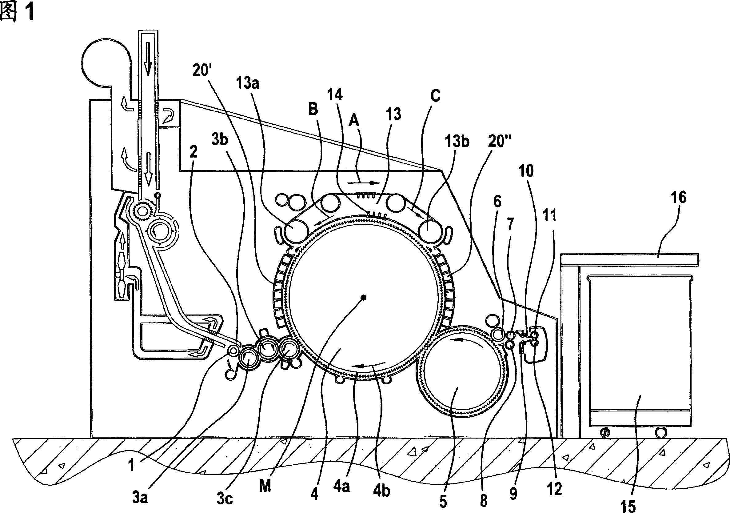
[0026] Figure 1 shows a flat card, for example a Trutzschler flat card TC 03, with a feed roller 1, a feed pan 2, licker-in rollers (licker-in) 3a, 3b, 3c, cylinder 4, small cylinder 5, stripper Take-off rollers 6, extrusion rollers 7, 8, web deflection device 9, web funnel 10, delivery rollers 11, 12, revolving cover with flat guide rollers 13a, 13b and flat bars 14 Plate 13 , bucket 15 and can coiler 16 . The direction of rotation of the rollers is indicated by the respective curved arrows. The letter M designates the midpoint (axis) of the drum 4 . Reference numeral 4a denotes a felt cloth, and 4b denotes the direction of rotation of the drum 4 . Arrow A indicates the working direction. Curved arrows drawn on the rollers indicate the direction of rotation of the rollers.

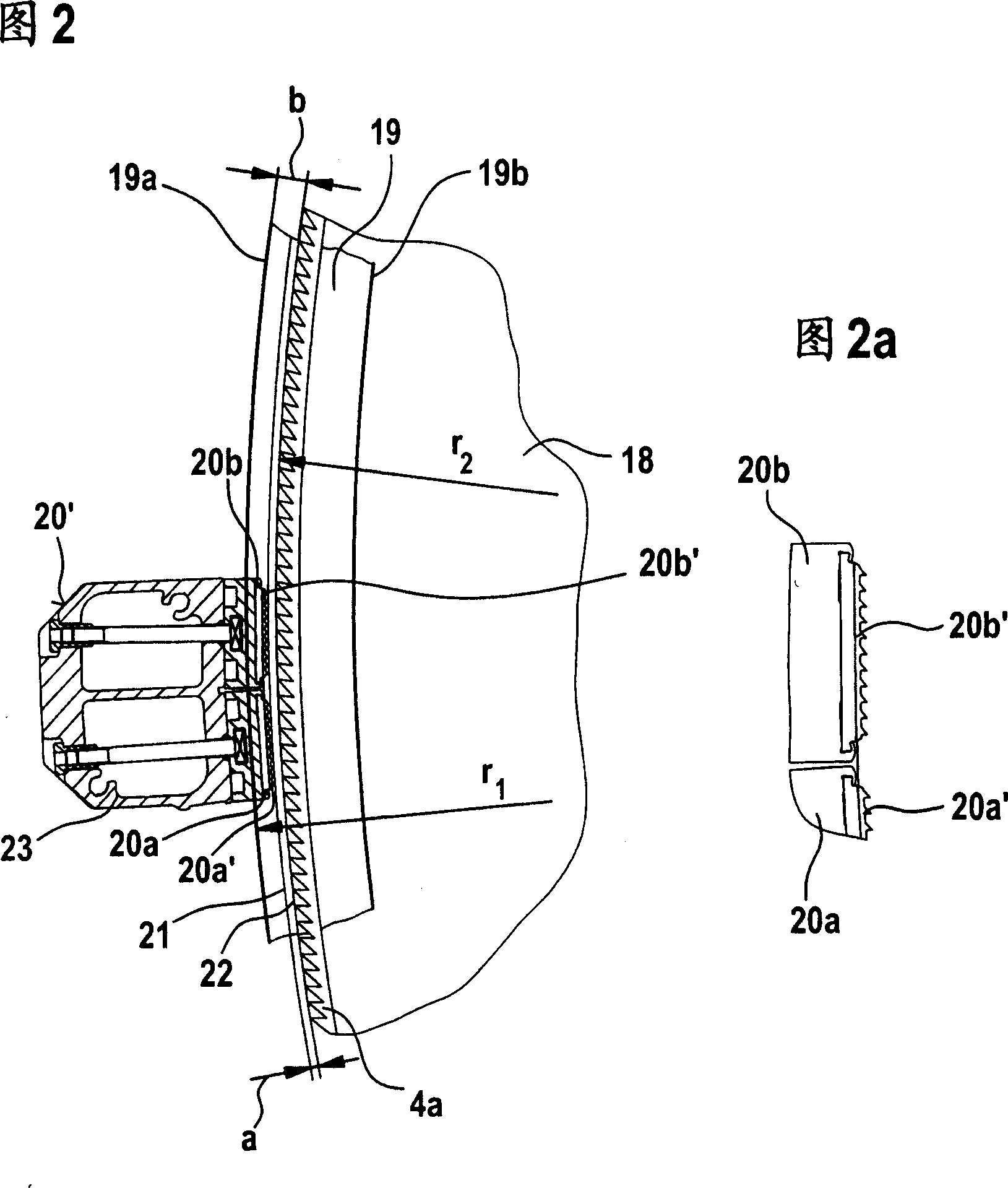
[0027] Referring to Fig. 2, on each side of the carding machine transversely to the frame (not shown) is fixed with a roughly semicircular rigid side plate 18; on the outside in its circumferential ar...


PUM


Abstract

An apparatus on a spinning preparation machine for monitoring and/or adjusting clearances at components has a clothed, high-speed roller located facing at least one clothed and/or unclothed component and the clearance between the components facing one another is alterable. The roller and opposed component(s) are electrically isolated with respect to one another and are connected as contact elements to an electrical power supply line in which a measuring device for ascertaining contact is located. In order to avoid an undesirably heavy contact between the components, electric signals are emitted upon contacts with the clothing of the roller and the measuring device is arranged quantitatively to determine the contacts.

Description

technical field [0001] The invention relates to a device for monitoring and / or adjusting gaps on parts located on a spinning preparation machine, in particular a flat card, roller card or similar, wherein the high-speed rollers of the covering felt face at least one covering The felt and / or non-felt parts are positioned and the gap between the parts facing each other is variable, where the parts arranged with the gap are electrically isolated from each other and are connected as contact elements to the power feed line, where the positioning is useful for determining the contacting measuring element. Background technique [0002] When cleaning or carding fibrous materials, such as cotton and / or synthetic fibres, the stationary cleaning or carding elements are usually placed facing the rotating rollers on which the felt is mounted. In order to achieve a good cleaning and / or carding action, these elements must be arranged as close as possible to the felt of the rotating roller...

Claims


Application Information

Patent Timeline
IPC IPC(8): D01G15/28D01G31/00
CPCD01G15/28
Inventor C·莱因德斯D·维尔茨T·施米茨
Owner TRUETZSCHLER GRP SE
Why Eureka
Try Eureka