Adjustable rotor coiling mould

An adjustable, winding die technology, used in the manufacture of motor generators, electrical components, electromechanical devices, etc., can solve the problems of increased man-hours, energy and material consumption, inaccurate positioning, low mold utilization, etc., to improve the mold Utilization rate, safe and reliable positioning, convenient adjustment and operation

Inactive Publication Date: 2007-08-01
安明科
View PDF1 Cites 4 Cited by
  • Summary
  • Abstract
  • Description
  • Claims
  • Application Information

AI Technical Summary

Problems solved by technology

[0002] The existing rotor winding dies are fixed, and rotors with different specifications and diameters need rotor winding dies with corresponding diameters, which is very inconvenient in actual use, because it is impossible to realize multiple functions of one die, so it is impossible to use motors of various specifications The rotor is clamped and wound on a set of molds; the utilization rate of the mold is low; in actual work, the winding of rotors with different specifications and diameters must be completed by changing the mold, which causes many problems; Man-hours, energy and material consumption required for the design and manufacture of winding dies
[0003] Such as the "Adjustable Motor Winding Die" of Chinese utility model patent ZL99203334.9, which consists of modules to form a mold core, and then use bolts to pass through the chute on the splint and fix it with the splint. There are radial and long screw holes on the module. And one side of the module is provided with a pair of guide pillars, and a guide groove is provided on the other side corresponding to the guide pillars; The side length can be adjusted without rotation between adjacent modules, but the structure is loose, the adjustment operation is inconvenient, and the positioning is not accurate. It can only be used as a winding tool and cannot directly complete the rotor winding

Method used


Image

  • Adjustable rotor coiling mould
  • Adjustable rotor coiling mould

Examples


Embodiment Construction

[0021] The present invention will be further described in detail below in conjunction with the accompanying drawings and embodiments.

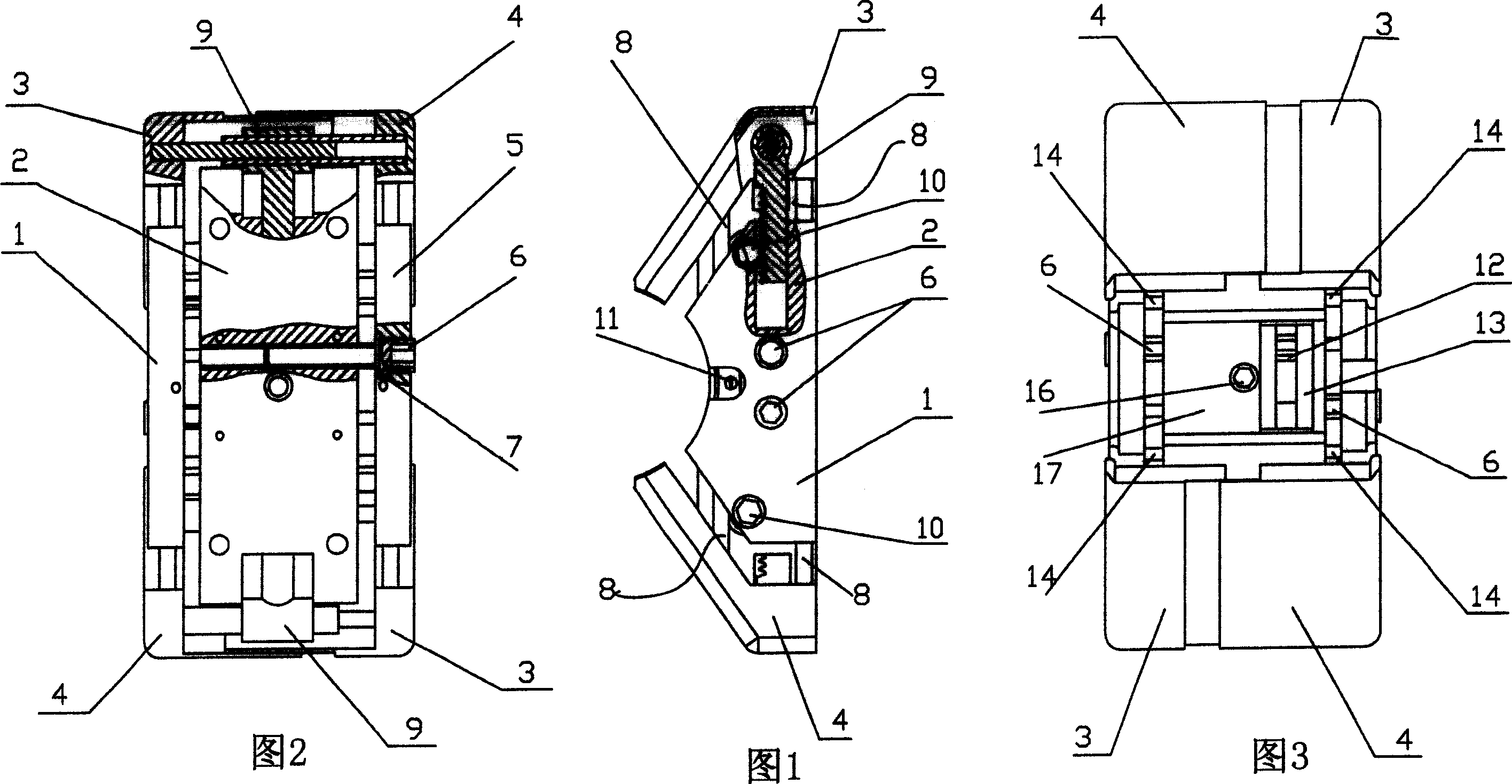
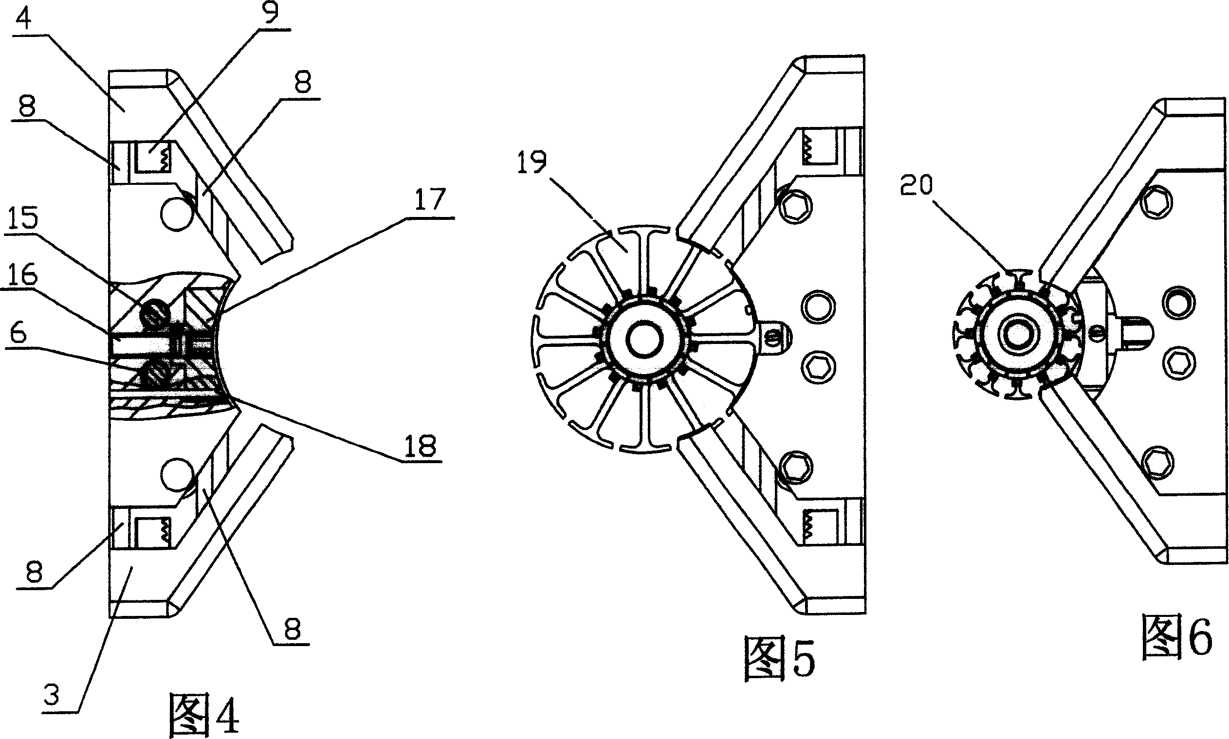
[0022] Figures 1 to 6 show the schematic structure of the adjustable rotor winding die. Structural features and working principles of the adjustable rotor winding die.

[0023] Description of structural features: The adjustable rotor winding die includes the mold body 2, wherein: the upper and lower end surfaces of the mold body 2 are respectively equipped with a set of first model surface 3 and second model surface 4 that are linked in the upper and lower directions and can be adjusted in the front and rear directions; The first model surface 3 and the second model surface 4 are equipped with four first guide columns 8 for up and down displacement, and are respectively linked with the first end plate 1 and the second end plate 5; the mold body 2 is symmetrically installed with rotation Functional gear shaft 10, the gear shaft 10 is engaged w...


PUM


Abstract

An adjustable rotor winding former is disclosed, the upper end surface and the lower end surface matches with a group of the first model surface and the second surface which can linkage up and down, fore and back; four guiding columns of the first, the second, the third are assorted; the gear shaft set on the mould joggles with linked T type rack; a adjustable bolt is separately mounted on the first end plate and the second end plate; the relative adjustable bolt axial position is limited at the first end plate and the second end plate via the first spacer pin, the screw thread part of the adjustable bolt is connected with the tap of mould; the arc locating plate component which embeds locking screw, tongue element, arc locating plate, the third guiding column, the adjustable bolt is whorled with the mould and is assembled to the arc locating plate via spacer pin. It can realize the clamping and winding of rotor with multiple specifications, without changing mould; the structure is compact, the adjustment is easy, and the location is safe and reliable.

Description

technical field [0001] The invention relates to the field of rotor winding dies, in particular to a multi-purpose adjustable rotor winding die. Background technique [0002] The existing rotor winding dies are fixed, and rotors with different specifications and diameters need rotor winding dies with corresponding diameters, which is very inconvenient in actual use, because it is impossible to realize multiple functions of one die, so it is impossible to use motors of various specifications The rotor is clamped and wound on a set of molds; the utilization rate of the mold is low; in actual work, the winding of rotors with different specifications and diameters must be completed by changing the mold, which causes many problems; The man-hours, energy and material consumption required for the design and manufacture of winding dies. [0003] Such as the "Adjustable Motor Winding Die" of Chinese utility model patent ZL99203334.9, which consists of modules to form a mold core, and...

Claims


Application Information

Patent Timeline
Patent Type & Authority Applications(China)
IPC IPC(8): H02K15/04
Inventor 安明科
Owner 安明科
Why Eureka
Try Eureka