Eureka AIR delivers breakthrough ideas for toughest innovation challenges, trusted by R&D personnel around the world.

Automatic close-type hinge

An automatic closing and hinge technology, which is used in wing shutters, lighting and heating equipment, door/window accessories, etc., which can solve the problem of rising parts manufacturing and assembly costs, large number of parts, and difficulty in distinguishing whether the hinge is right-opening or not. Left opening specifications and other issues

Active Publication Date: 2007-08-08
TAKIGEN MFG CO LTD
View PDF1 Cites 13 Cited by
  • Summary
  • Abstract
  • Description
  • Claims
  • Application Information

AI Technical Summary

Problems solved by technology

[0004] However, in the conventional self-closing hinge, once the fixed cam body is installed in the fixed side panel, it is difficult to distinguish whether the hinge is a right-opening specification or a left-opening specification from the appearance, so it is sometimes misunderstood. The case where a hinge assembled to a different specification is brought to the site of use, and the fixed cam body has to be replaced in a hurry with a jig at the site of use
[0005] In addition, in the conventional self-closing hinge, as components, in addition to the fixed side flap, the movable side flap and the fixed cam body, since there are also rotatably fitted in the vertical shaft hole of the fixed side flap, A cam follower with a cam slope abutting against the cam slope of the fixed cam body is formed on the lower surface, penetrates and is fixed at the center of the cam follower, and inserts and fixes the upper part into the movable side wing plate. In the vertical shaft hole, the lower part of the shaft rod is rotatably inserted into the vertical shaft hole of the fixed cam body. Therefore, the number of constituent parts is large, and the manufacturing and assembly costs of the parts are increased.

Method used


Image

  • Automatic close-type hinge
  • Automatic close-type hinge
  • Automatic close-type hinge

Examples


Embodiment Construction

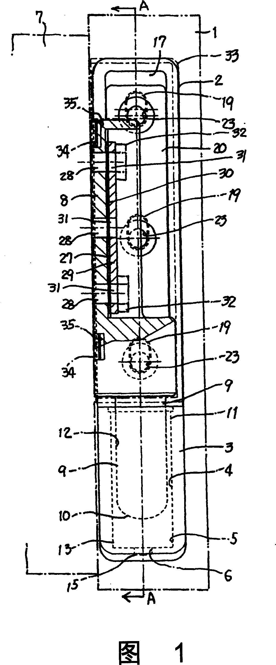
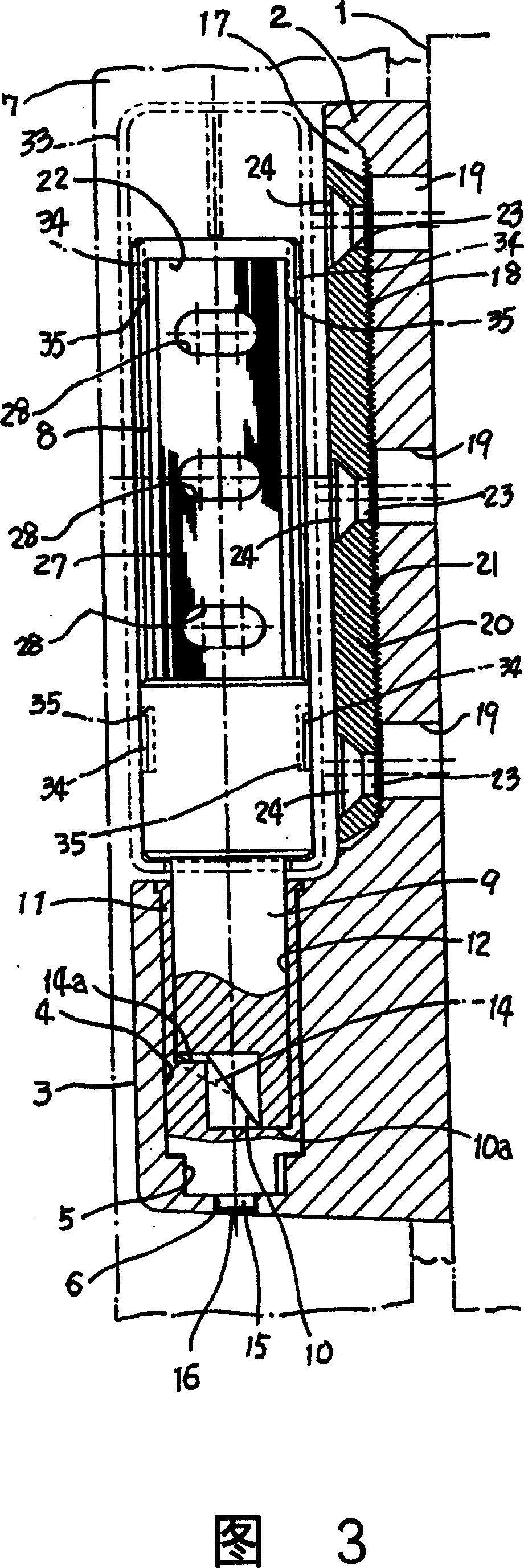
[0048] In the illustrated embodiment, the fixed side wing plate 2 and the movable side wing plate 8 are made of metal, the fixed cam body 11 is made of synthetic resin, and the sliding contact portion of the push-up cam is made of resin and metal. The contact between the cams is made of resin, so there is no wear or significantly reduced wear compared to conventional self-closing hinges.

[0049] After the locking of the door locking handle device installed in addition is released, when the door 7 is rotated to the required angle in the opening direction with the vertical pivot 9 as the center, the drive cam slope 14 of the fixed side wing plate 2 and the vertical pivot The linkage action of the driven cam slope 10 of the shaft 9 makes the vertical pivot 9 and the movable side panel 8 integrated with the vertical pivot 9 rotate and push up to the position shown in FIG. 4 .

[0050] In this open position, if the hand leaves the door 7, the door 7 will automatically close and ro...


PUM


Abstract

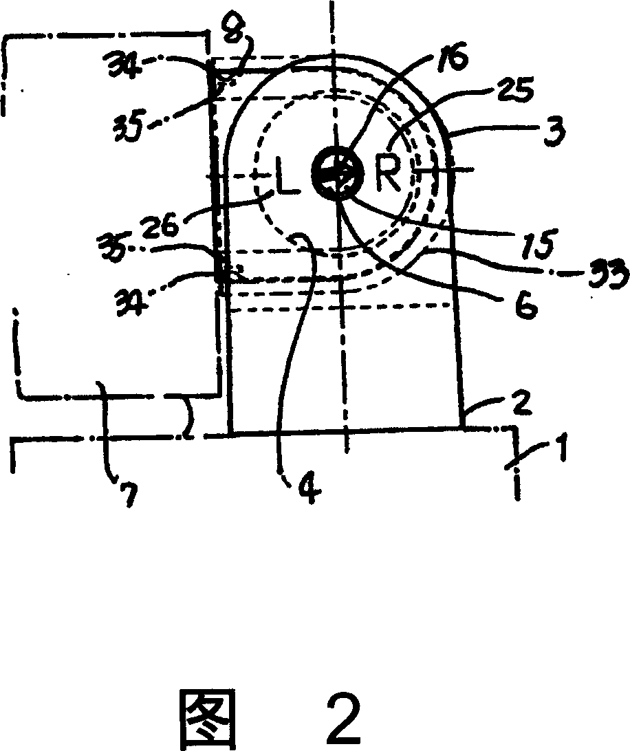
An automatic closing type hinge has a vertical cam support hole (4) formed on a fixed flank plate (2), a non-circular hole (5) formed on the bottom of the vertical cam support hole (4), a through hole (6) opening to the bottom of the fixed flank plate (2) and formed on the bottom of the non-circular hole (5), and a driven cam inclined surface (10) formed at the lower end of a vertical pintle (9) formed at the lower part of a movable flank plate (8). The fixed cam (11) is formed with a vertical bearing hole for embedding the rotatable vertical pintle (9), the lower part of the fixed cam (11) is formed with a non-circular pillar part (13) which can change 180 degrees phase in horizontal plane and can be inserted in and drawn from the non-circular hole (5). A drive cam inclined surface (14) contacting the driven cam inclined surface (10) is formed on the bottom of the vertical bearing hole (12), a representation prominency (15) embedded into the through hole (6) is formed on the non-circular pillar part (13), a direction arrow (16) is disposed on the bottom of the representation prominency (15), the bottom of a support seat part (3) is disposed with a right open type specification sign (25) and a left open type specification sign (26). Adopting the invention, even at assembly status, the right open type specification and the left open type specification can be identified conveniently from appearance.

Description

technical field [0001] The invention relates to a door used for refrigerators, and a hinge for automatically closing and rotating the door by using an inclined cam and the self-weight of the door. Background technique [0002] We know a self-closing hinge (refer to Patent Document 1), which includes: a fixed side panel fixed on the fixed frame; a movable side panel fixed on the door; a vertical shaft arranged on the fixed side panel On the bottom of the hole, a fixed cam body with an inclined surface formed on the upper surface; a cam follower, rotatably embedded in the vertical axis hole of the fixed side wing plate, and a cam inclined surface abutting against the fixed cam body formed on the lower surface the cam slope; and the shaft rod, which is fixed through the central part of the cam follower, the upper part is inserted and fixed in the vertical shaft hole of the movable side wing plate, and the lower part is rotatably inserted into the fixed In the vertical shaft ho...

Claims


Application Information

Patent Timeline
IPC IPC(8): E05F1/06E05D7/04F25D23/02
CPCE05D7/02E05F1/06E05Y2201/638
Inventor 杉村笃朗
Owner TAKIGEN MFG CO LTD
Why Eureka
Eureka Blog
Learn More