Method of reeling a series of RFID tags and RFID tag roll

A technology of RFID tags and series, applied in the field of RFID tag rolls

Inactive Publication Date: 2007-08-08
FUJITSU LTD +1
View PDF3 Cites 2 Cited by
  • Summary
  • Abstract
  • Description
  • Claims
  • Application Information

AI Technical Summary

Problems solved by technology

Therefore, this has a considerable impact on the processing of RFID tags that should be manufactured at low cost and in high volume

Method used


Image

  • Method of reeling a series of RFID tags and RFID tag roll
  • Method of reeling a series of RFID tags and RFID tag roll
  • Method of reeling a series of RFID tags and RFID tag roll

Examples


Embodiment Construction

[0040] Exemplary embodiments according to the present invention will be described with reference to the drawings.

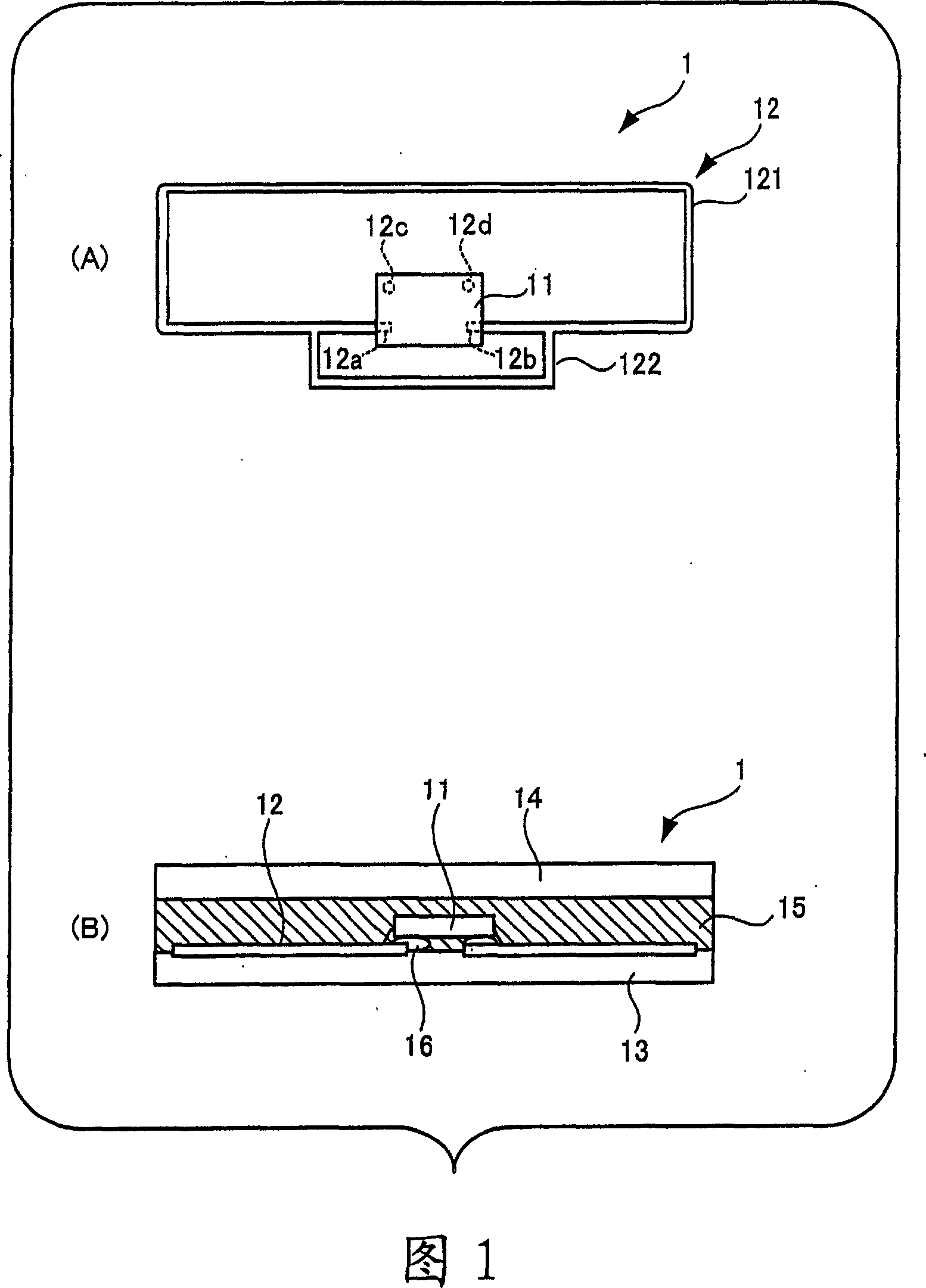
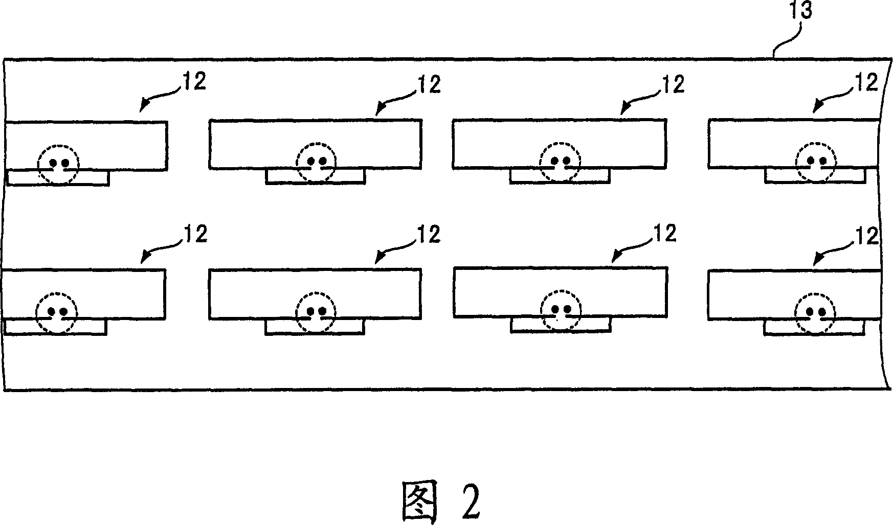
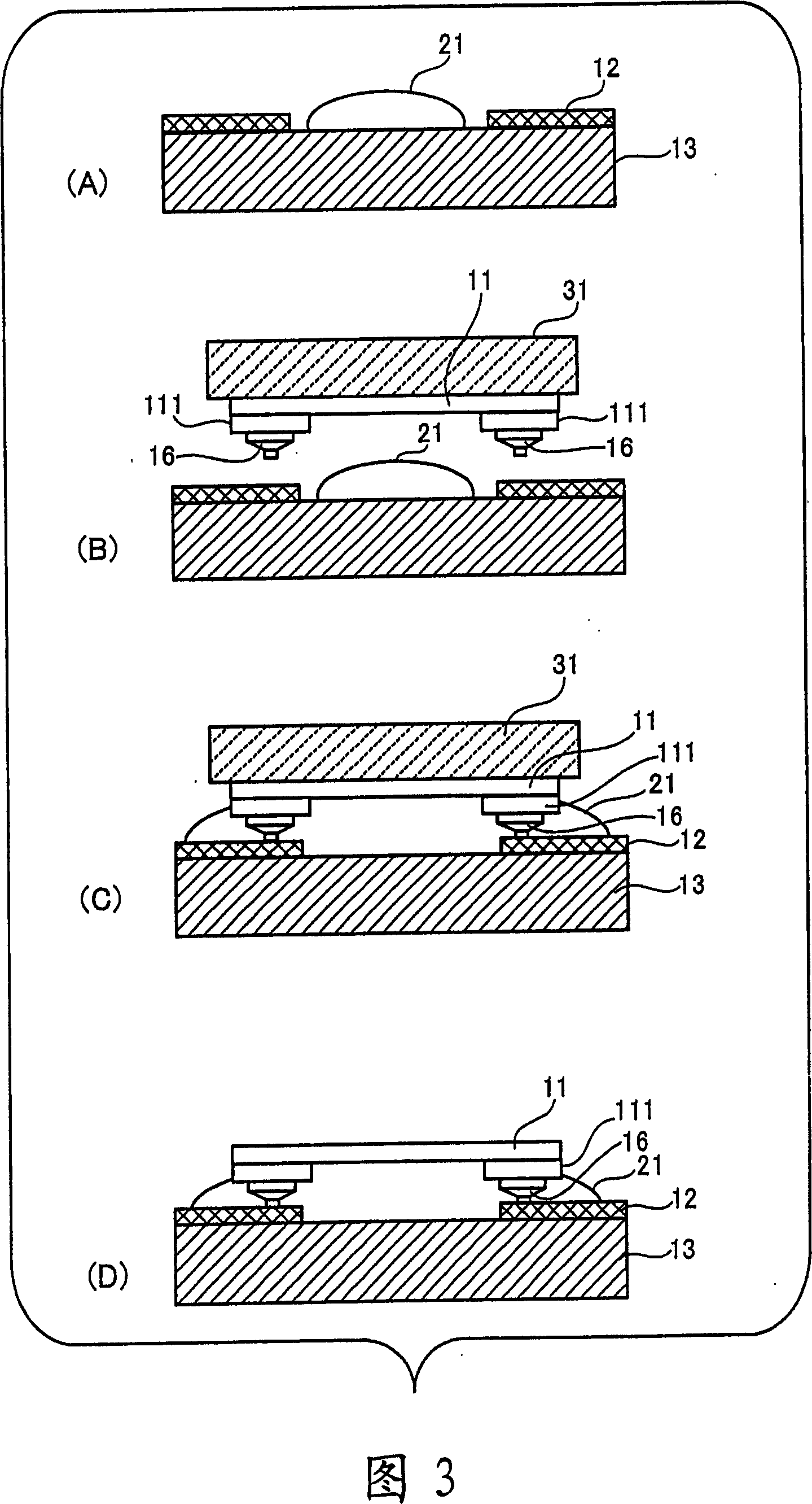
[0041] In the exemplary embodiments described below, the RFID tags and the RFID tag family itself are similar to the RFID tags in the prior art described above. Therefore, only the differences from the prior art will be described with reference to FIGS. 1 to 4 and their descriptions.

[0042] Fig. 6 is a diagram showing an RFID tag roll in which the RFID tag series is wound.

[0043] The RFID tag series 100 is wound around a spool core 40 formed of a core material 41 and a stress absorbing material 42 laminated around the core material 41 to form a roll 120 of RFID tags. The diameter of the core material 41 shown in FIG. 6 is smaller than that of the core material shown in FIG. 5 by the portion where the stress absorbing material 42 is placed around the core material 41 .

[0044] In an exemplary embodiment, a material that shrinks and deforms under an external f...


PUM


Abstract

Method of reeling a series of RFID tags and RFID tag roll are provided in the invention. A series of RFID tags is reeled around a reel core formed by a core material and a stress absorbing material lapped around the core material to absorb a stress produced in reeling the series of RFID tags. In the series of RFID tags, a number of RFID tags each having an antenna and a circuit chip connected to the antenna and performing radio communication with the antenna are formed with a predetermined pitch on a long-belt-like and flexible base.

Description

technical field [0001] The present invention relates to a method of winding a series of RFID tags and to a roll of RFID tags. On the RFID tag series are formed a plurality of RFID (Radio Frequency Identification) tags that can exchange information with an external device without being in contact with the device, and are arranged at predetermined intervals on a long strip-shaped flexible substrate . The RFID tag roll is formed by winding the RFID tag series. For those skilled in the art, the "RFID tag" used in the present invention is also called "RFID tag inlay", which is the internal component of the "RFID tag". This "RFID tag" is also called a "wireless IC tag". RFID tags include contactless IC cards. Background technique [0002] In recent years, various RFID tags have been proposed that do not come into contact with external devices represented by readers and recorders, but exchange information with the devices by using radio waves (see, for example, Japanese Patent ...

Claims


Application Information

Patent Timeline
Patent Type & Authority Applications(China)
IPC IPC(8): G06K19/07
CPCH01L2224/92247H01L24/97G06K19/07749H01L2224/75252H01L2924/01082G06K19/07728H01L2924/01047G06K19/07718H01L2224/97H01L2224/48465H01L2224/16H01L2224/48227H01L2924/01005H01L2924/01033H01L2924/01006H01L2924/01029H01L2224/16227H01L2224/16225H01L2224/48091H01L2224/73265H01L2924/01013G06K19/0775H01L2224/32225H01L24/73H01L2224/05573H01L2224/05568H01L2924/00014H01L2224/83H01L2224/85H01L2224/81H01L2924/00H01L2924/00012H01L2224/05599G06K19/077G06K19/07
Inventor 石川直树常野达朗吉良秀彦
Owner FUJITSU LTD
Why Eureka
Try Eureka