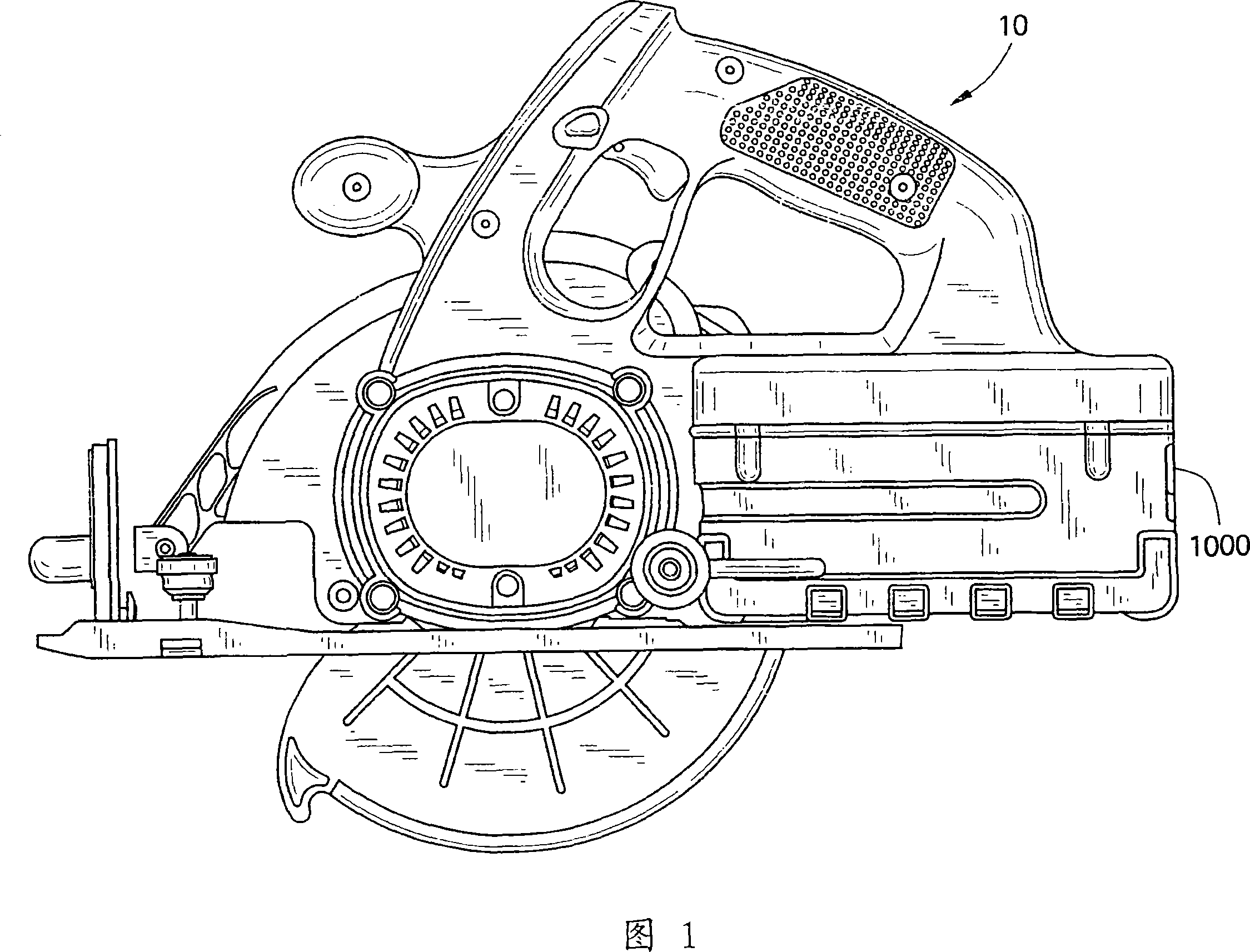
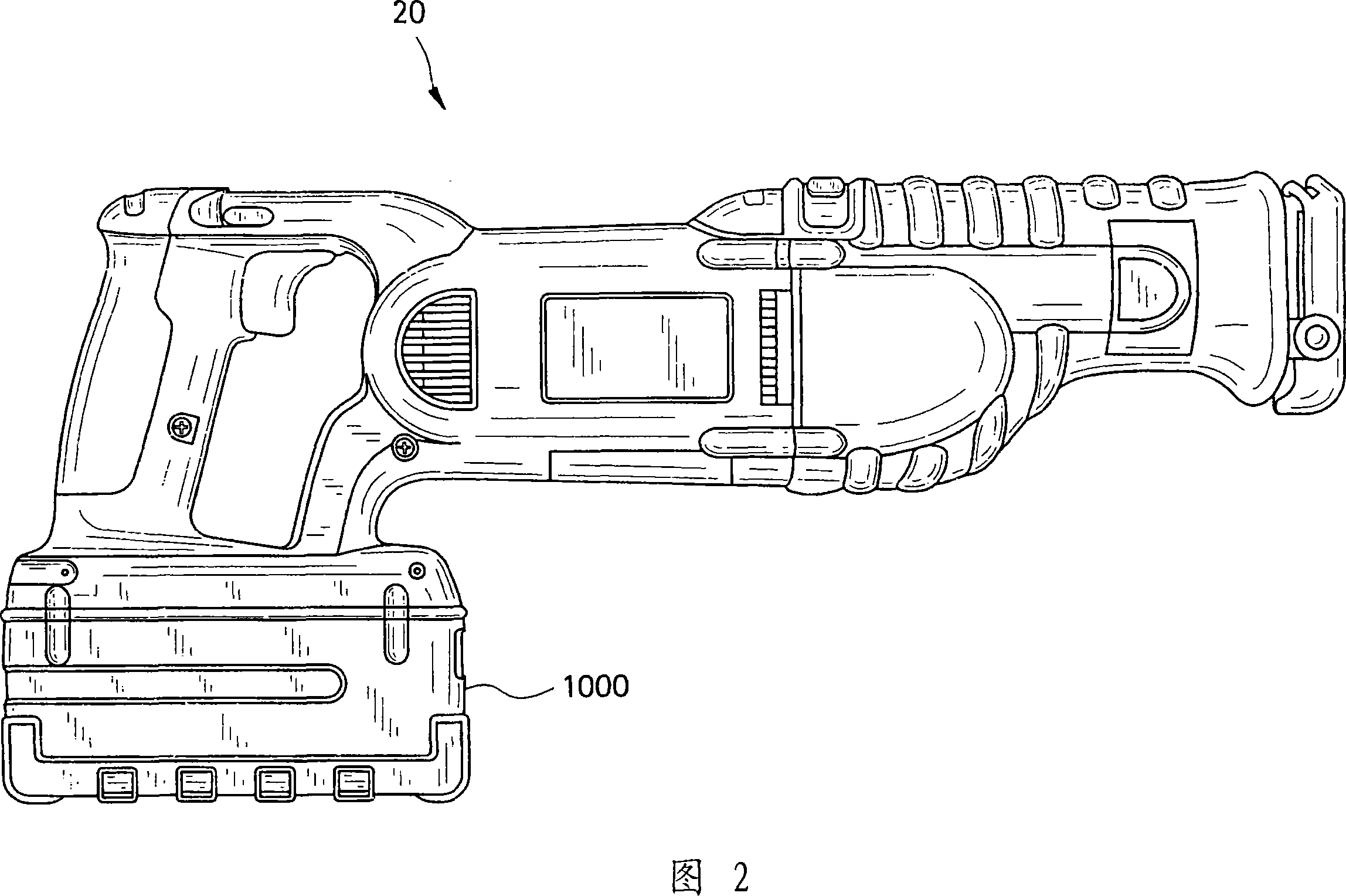
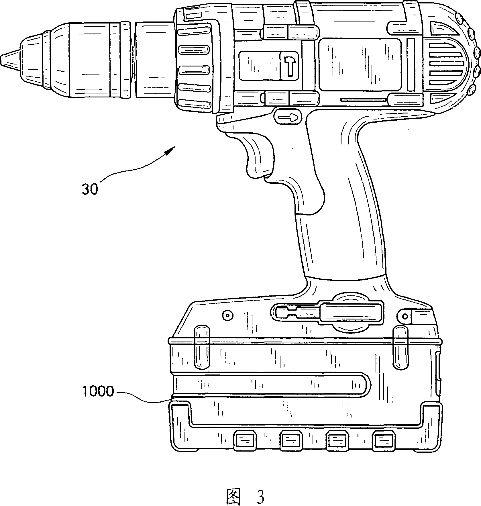
Methods of charging battery packs for cordless power tool systems

A battery pack and battery voltage technology, applied in secondary battery charging/discharging, battery circuit devices, electric vehicles, etc., can solve complex charging circuits, complex problems, etc.

Inactive Publication Date: 2007-08-08
BLACK & DECKER INC
View PDF1 Cites 31 Cited by
  • Summary
  • Abstract
  • Description
  • Claims
  • Application Information

AI Technical Summary

Problems solved by technology

Especially when charging a battery pack with multiple cells connected in series, each of ...

Method used


Image

  • Methods of charging battery packs for cordless power tool systems
  • Methods of charging battery packs for cordless power tool systems
  • Methods of charging battery packs for cordless power tool systems

Examples


example 1

[0063] In this example, for a multi-cell Li-ion battery pack (e.g., 10 cells connected in series and / or cells in a 2-parallel-10-series (2P10S) configuration) with a lithium metal phosphate cell chemistry such as LFP, the An exemplary charging principle is to charge the cells within the allowable voltage window up to a maximum individual cell voltage of 3.8V, and continue charging until all cells are above some minimum value such as 3.6V, whereupon all cells obtain 100% charge. Cell balancing can be performed on those cells that reached 3.8V first, while some cells did not reach the minimum value of 3.6V. Cell balancing can be performed as described in the '286 application.

[0064] The difference between the capacity of a battery charged to 3.8V and a battery charged to a maximum of 3.6V is only 0.1Ah or less due to the voltage polarity characteristic of the 100% state of charge. Charging to the voltage window minimizes the time at the higher charging voltage, thus reducing...

example 2

[0083] FIG. 12 is a graph illustrating the voltage curve and charging current of the battery pack 1000 over time for another exemplary charging method. Charging current (amps) and voltage (volts) are shown in FIG. 12 as a function of charging time (seconds). Figure 12 is labeled with regions 1-5 to aid in explaining some of the functions performed during this exemplary charging process. This exemplary method is similar to the examples in Figures 10 and 11; only the differences are described below. As in Example 1, the present charging method described was used to charge a multi-cell Li-ion battery pack (10 cells connected in series and / or 2Parallel-10Series (2P10S) configuration) with lithium metal phosphate cell chemistry. battery) and perform voltage monitoring of individual cells and / or entire pack voltages and cell balancing as described in the '286 application. The battery arrangements and battery chemistries described here are exemplary only; the charging methods below...


PUM


Abstract

In a method of charging a battery pack, the pack is inserted in a charger and an initial set of checks of cell voltage and pack temperature is performed. Once the initial set of checks is satisfied, the cells may be charged at a first constant current level. The first constant current level is adjusted to one or more lower levels of constant current until cell voltages of all the cells are within a full charge voltage window. The voltage window is defined between a minimum full charge cell voltage level and a maximum full charge cell voltage level. The charge may be terminated once all of the cells are within the full charge voltage window.

Description

technical field [0001] Exemplary embodiments of the present invention generally relate to a method of charging a battery pack of a cordless power tool. Background technique [0002] Charging algorithms for traditional Li-ion battery packs typically use a constant current / constant voltage (CC / CV) charging algorithm, where when the battery pack voltage increases to a set voltage threshold level (typically 90% of state of charge) , the charging current is maintained at a constant level for a period of time. At this point, the battery pack voltage is held at a constant voltage level while the current tapers down to a lower level to complete charging. [0003] In order to charge a conventional Li-ion battery pack, the power source (charger) that supplies the charging current to the battery pack needs to maintain (at various times during charging) a constant voltage and / or a constant current. This requires complex or cumbersome charging circuits, especially when charging a batte...

Claims


Application Information

Patent Timeline
IPC IPC(8): H01M10/44H02J7/00
CPCH02J7/04H02J7/0073H02J7/0071
Inventor 珍妮特·M·恩布里丹·T·特林
Owner BLACK & DECKER INC
Why Eureka
Try Eureka