Ball screw

A technology of ball screw and transmission device, which is applied in the direction of transmission device, transmission device parts, transportation and packaging, etc., and can solve the problem of troublesome relubrication of ball screw transmission device

Inactive Publication Date: 2007-08-08
SCHAEFFLER TECH AG & CO KG
View PDF1 Cites 10 Cited by
  • Summary
  • Abstract
  • Description
  • Claims
  • Application Information

AI Technical Summary

Problems solved by technology

Relubrication of the ball screw drive is complex, since the housing must be opened for external access

Method used


Image

  • Ball screw
  • Ball screw

Examples


Embodiment Construction

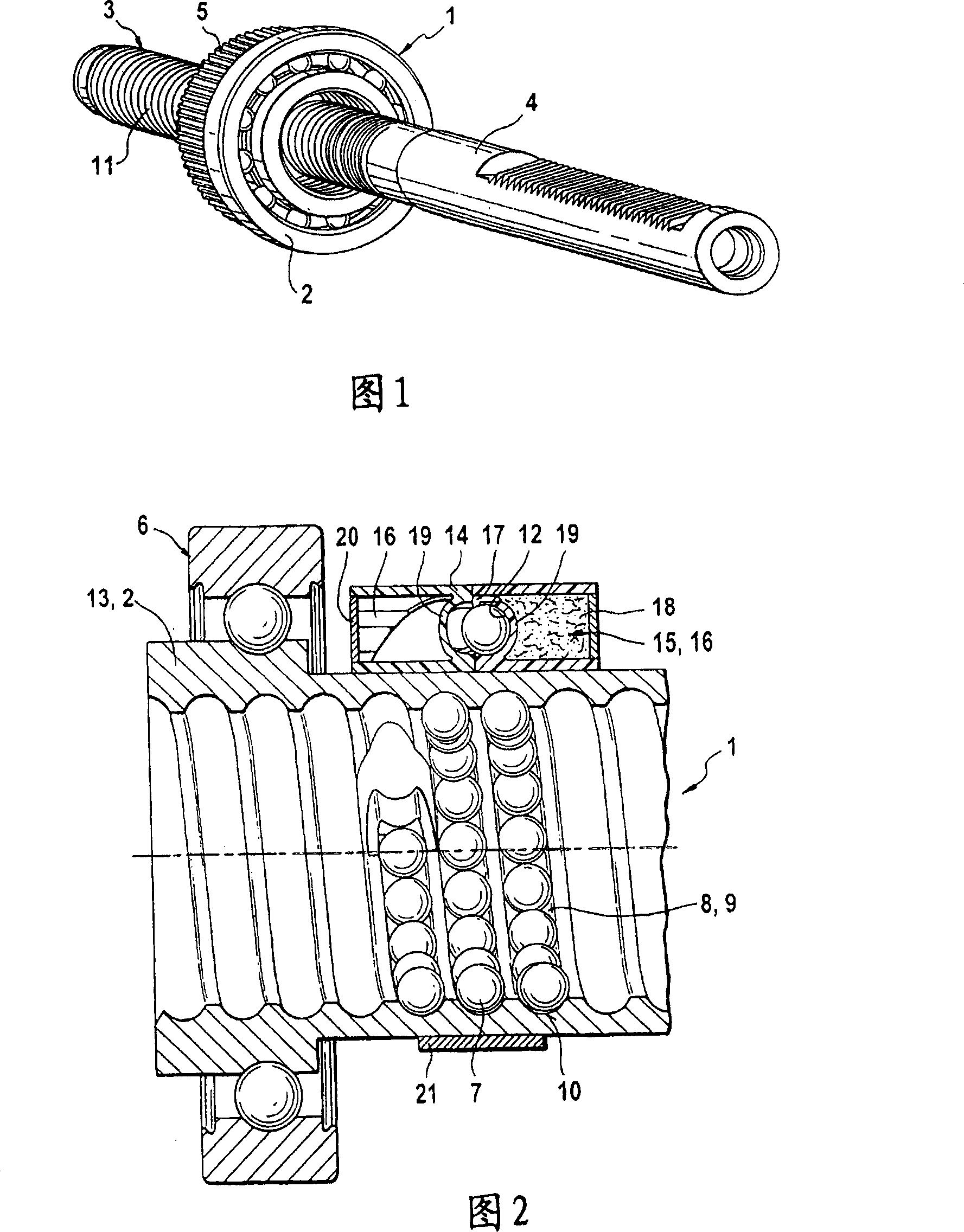
[0018] FIG. 1 shows the main components of a power-assisted rack and pinion steering of a motor vehicle in a perspective view. A ball screw drive 1 has a spindle nut 2 which is rotatably mounted on a ball screw 3 . The ball screw 3 is formed purely as an axial extension of the toothed rack. It can also be seen from FIG. 1 that the spindle nut 2 is equipped with a drive pinion 5 for a toothed belt (not shown here). This drive pinion 5 is connected to the spindle nut 2 in a rotationally fixed manner.

[0019] The spindle nut is installed here in a housing which is not further shown here.

[0020] FIG. 2 shows a longitudinal sectional view of the ball screw drive 1 in an enlarged view. The spindle nut 2 is mounted rotatably via deep-groove ball bearings 6 in a housing (not shown here). The balls 7 can be arranged continuously around in the continuous ball channel 8 . This continuous ball channel 8 has a load section 9 which is delimited by the ball raceways 10 , 11 of the sp...


PUM


Abstract

The invention relates to a ball screw (1) comprising a ball caster spindle (3) and a driven spindle nut (2) arranged thereon. Balls (7) are arranged in a continuously rotatable manner in at least one endless ball channel (8), said ball channel (8) comprising a load section (9) which is wound around the ball caster spindle (3) and defined by ball tracks (10, 11) of the ball caster spindle (3) and the spindle nut (2), and a load-free recycling section (12) which continuously connects the beginning and end thereof. A regreasing device (15) which is arranged on the spindle nut (2) in a rotationally fixed manner supplies lubricant to the ball channel (8) using centrifugal force.

Description

technical field [0001] The invention relates to a ball screw transmission device. The ball screw drive is a rotary-translational drive in which a rotary motion can be converted into a linear motion. Ball screw drives of this type are increasingly used in the automotive sector, especially in electromechanical steering boosters. Background technique [0002] For example, DE 102 58 826 A1 discloses a drive with a rolling-element screw drive, which can be used as an electromechanical steering booster in a rack and pinion steering gear of a motor vehicle. The hollow rotor is mounted rotatably in the housing via rolling bearings, wherein the rotor is drive-connected to the spindle nut. The rotor drives the threaded spindle of the rolling element screw drive. The lead screw nut is arranged inside the casing. With the ball screw drive disclosed here, the balls roll on the ball raceways of the screw nut and ball screw. This ball screw drive is equipped with disposable grease lub...

Claims


Application Information

Patent Timeline
Patent Type & Authority Applications(China)
IPC IPC(8): F16H25/22B62D5/04F16H25/24
CPCF16H25/2418F16H57/0497B62D5/0448F16H25/2214F16H25/2204
Inventor J·奥斯特伦格D·阿德勒M·克劳斯R·迈尔
Owner SCHAEFFLER TECH AG & CO KG
Why Eureka
Try Eureka