Coherent scatter imaging

A coherent scattering and imaging system technology, applied in radiation measurement, nuclear radiation exploration, X/γ/cosmic radiation measurement, etc., can solve problems such as difficult to judge absorption features, unable to provide identification, etc.

Inactive Publication Date: 2007-08-08
KONINKLIJKE PHILIPS ELECTRONICS NV
View PDF3 Cites 3 Cited by
  • Summary
  • Abstract
  • Description
  • Claims
  • Application Information

AI Technical Summary

Problems solved by technology

However, such systems do not provide good discrimination and it is difficult to tell whether a specific absorption signature is due to explosives or any of a number of other common materials such as chocolate or plastic

Method used


Image

  • Coherent scatter imaging
  • Coherent scatter imaging
  • Coherent scatter imaging

Examples


Embodiment Construction

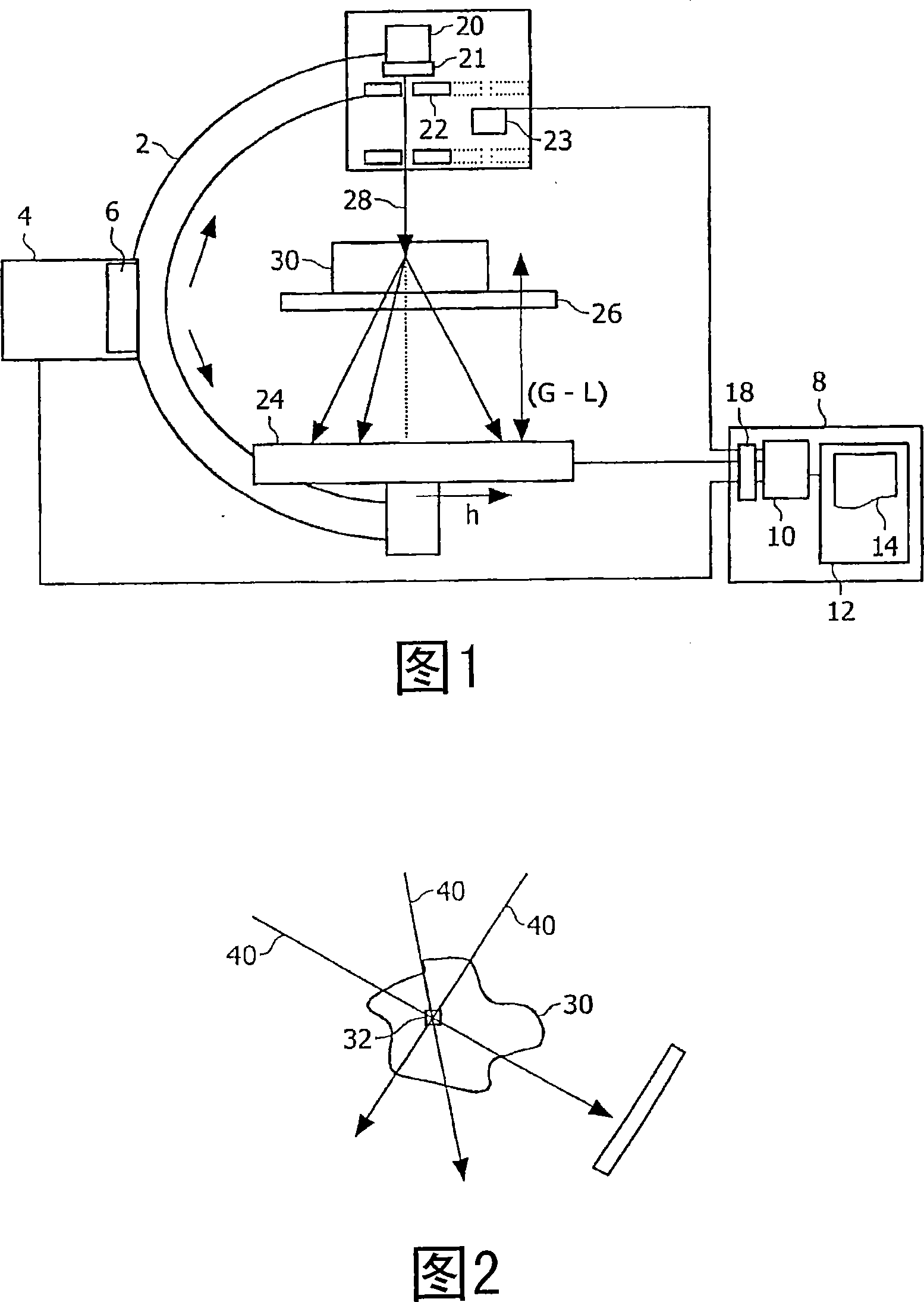
[0067] Referring to FIG. 1 , a first embodiment of the invention comprises a C-arm 2 mounted on a mount 4 and connected to a driver 6 for driving the C-arm into various positions under the control of a controller 8 at any position. The C-arm supports an X-ray source 20 , a collimator 22 and a detector 24 . The collimator 22 is movable by a drive 23 between two positions, in one of which the collimator 22 is inserted into the beam (shown in solid lines), and in the other position , which is outside the beam path (as indicated by the dashed line).

[0068] The C-arm 2 can be driven by a drive 6 to rotate the C-arm so that the source 20 and detector 24 are pointed at many different angles. It is also possible to drive the C-shaped arm so that the arm rotates in a direction away from the paper, thereby determining the direction of the source and the detector, so that various three-dimensional X-ray beam directions are possible.

[0069] The controller 8 includes a processor 10 ...


PUM


Abstract

A region of interest is identified using a conventional CT or X-ray approach. Then, the region of interest is scanned using a plurality of pencil beams (28) to obtain a plurality of different scattered X-ray spectra. A geometric correction is then applied to each spectrum as if the spectrum was solely due to features in the region of interest. The various spectra recorded using the beams are combined and correlated to determine features of the region of interest (32) whilst minimising the effect of features in the rest of the sample (30).

Description

technical field [0001] The present invention relates to apparatus and methods for coherent scatter imaging, in particular, but not limited to apparatus and methods for coherent scatter computed tomography. Background technique [0002] There is a continuing need for fast, reliable material scanners. One specific space of commercial interest is the rapid baggage scanner, which can be used in a variety of situations, but is often used to scan airline baggage. Another specific area of ​​commercial interest is in the area of ​​medical scanners. [0003] For example, the interaction of X-ray photons with matter in a certain energy range between 20 and 150 keV can be described by photoelectric absorption and scattering. There are two different types of scattering: on the one hand incoherent or Compton scattering and on the other hand coherent or Rayleigh scattering. However, Compton scattering varies slowly with angle, while Rayleigh scattering is strongly forward and has disti...

Claims


Application Information

Patent Timeline
Patent Type & Authority Applications(China)
IPC IPC(8): G01V5/00G01T1/164
CPCG01T1/1644G01V5/0025
Inventor 米夏埃多·格拉斯延斯-彼得·施洛姆卡乌多·范斯特文达勒
Owner KONINKLIJKE PHILIPS ELECTRONICS NV
Why Eureka
Try Eureka