The drilling processing machine for printed circuit boards
A technology for processing printed substrates and holes, which is applied in metal processing machinery parts, printed circuits, metal processing, etc., and can solve problems such as complex structures
Inactive Publication Date: 2007-08-15
TAKEUCHI
View PDF2 Cites 5 Cited by
- Summary
- Abstract
- Description
- Claims
- Application Information
AI Technical Summary
Problems solved by technology
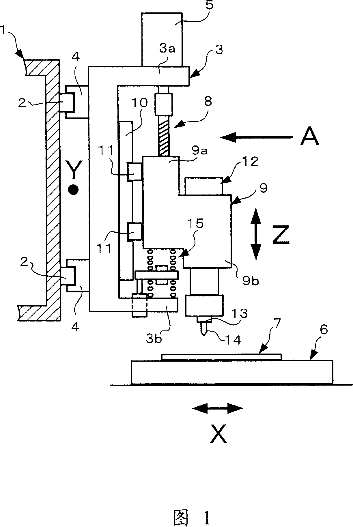
[0021] However, the vibration damping device (shock absorber) needs parts such as a spring support plate, a first member fitted with the spring support plate, a second member fitted with the lower horizontal end plat
Method used
View moreImage
Smart ImageViewing Examples
Examples
Example Embodiment
[0065] Example
Login to View More PUM
 Abstract
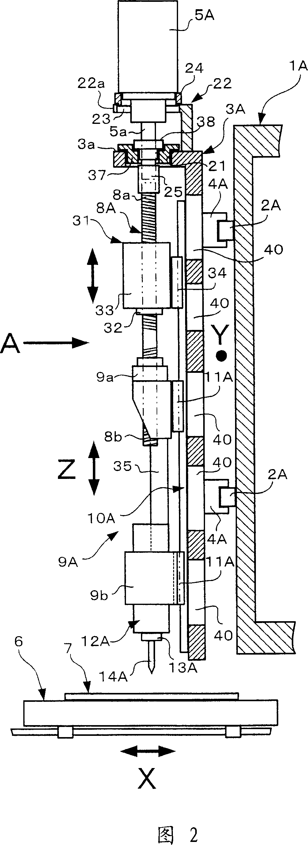
The invention relates to a drilling machine for printed board, which can prevent a drill from getting damaged caused by an ascent/descent of a lifting body. The drilling machine for a printed board includes a movable support, the lifting body provided to be vertically movable via a vertical guide rail of the movable support by driving force of a driving motor including a driving screw lever and a table provided below the lifting body and moving back and forth. A thread in one direction is formed on an upper part of the driving screw lever, a thread in the other direction is formed on a lower part of the lever, and a weight member capable of at least attenuating vibration caused on the thread in one direction by the ascent/descent of the lifting body is screwed together. In addition, a full length of the driving screw lever is located approximately immediately above a spindle mounted on the lifting body.
Description
technical field [0001] The present invention relates to a drilling machine for printed circuit boards. Background technique [0002] The drilling machine for printed circuit boards is constituted, for example, by a combination of the X-axis movement, Y-X-axis movement, and Z-axis movement shown in FIG. Axis motion is partially repeated). [0003] Generally, the movement of the X-axis or the Y-axis means the positioning of the plane, and the movement of the Z-axis means the vertical movement. In addition, -Z movement means the movement (descending) for cutting, and +Z movement means the movement (rising) which pulls the drill which has finished cutting from the printed circuit board. Among these actions, the +Z action can be said to be an action that is actually meaningless. This is because the +Z movement is not used for cutting, but simply returns the drill to its original position. Therefore, in order to provide a device with higher productivity, there is a problem of ...
Claims
Login to View More Application Information
Patent Timeline
 IPC IPC(8): B23B47/26B23B47/02H05K3/00
CPCB23B2250/16B23Q11/0032B26F1/16B26F2210/08H05K3/0047
Inventor 前野伸
Owner TAKEUCHI
Features
- R&D
- Intellectual Property
- Life Sciences
- Materials
- Tech Scout
- Unparalleled Data Quality
- Higher Quality Content
- 60% Fewer Hallucinations
Learn More Browse by: Latest US Patents, China's latest patents, Technical Efficacy Thesaurus, Application Domain, Technology Topic, Popular Technical Reports.
© 2025 PatSnap. All rights reserved.Legal|Privacy policy|Modern Slavery Act Transparency Statement|Sitemap|About US| Contact US: help@patsnap.com


