Horizontal-flow wind/light energy source composite generator device and uses thereof

A power generation device and wind power generation technology, applied in the energy field, can solve problems such as affecting photoelectric conversion efficiency, and achieve the effect of improving wind power conversion efficiency and photoelectric conversion efficiency

Inactive Publication Date: 2007-08-15
马元威
View PDF1 Cites 17 Cited by
  • Summary
  • Abstract
  • Description
  • Claims
  • Application Information

AI Technical Summary

Problems solved by technology

[0003] However, because the prior application is a single wind-repelling vertical wind-flow wind energy utilization structure, it has certain limitations on the utilization efficiency of wind energy, and because the installed solar cell membrane is always vertical to the ground, it cannot receive sunlight radiation. The angle also has certain limitations, which also affects the improvement of photoelectric conversion efficiency.

Method used


Image

  • Horizontal-flow wind/light energy source composite generator device and uses thereof
  • Horizontal-flow wind/light energy source composite generator device and uses thereof

Examples


Embodiment 1

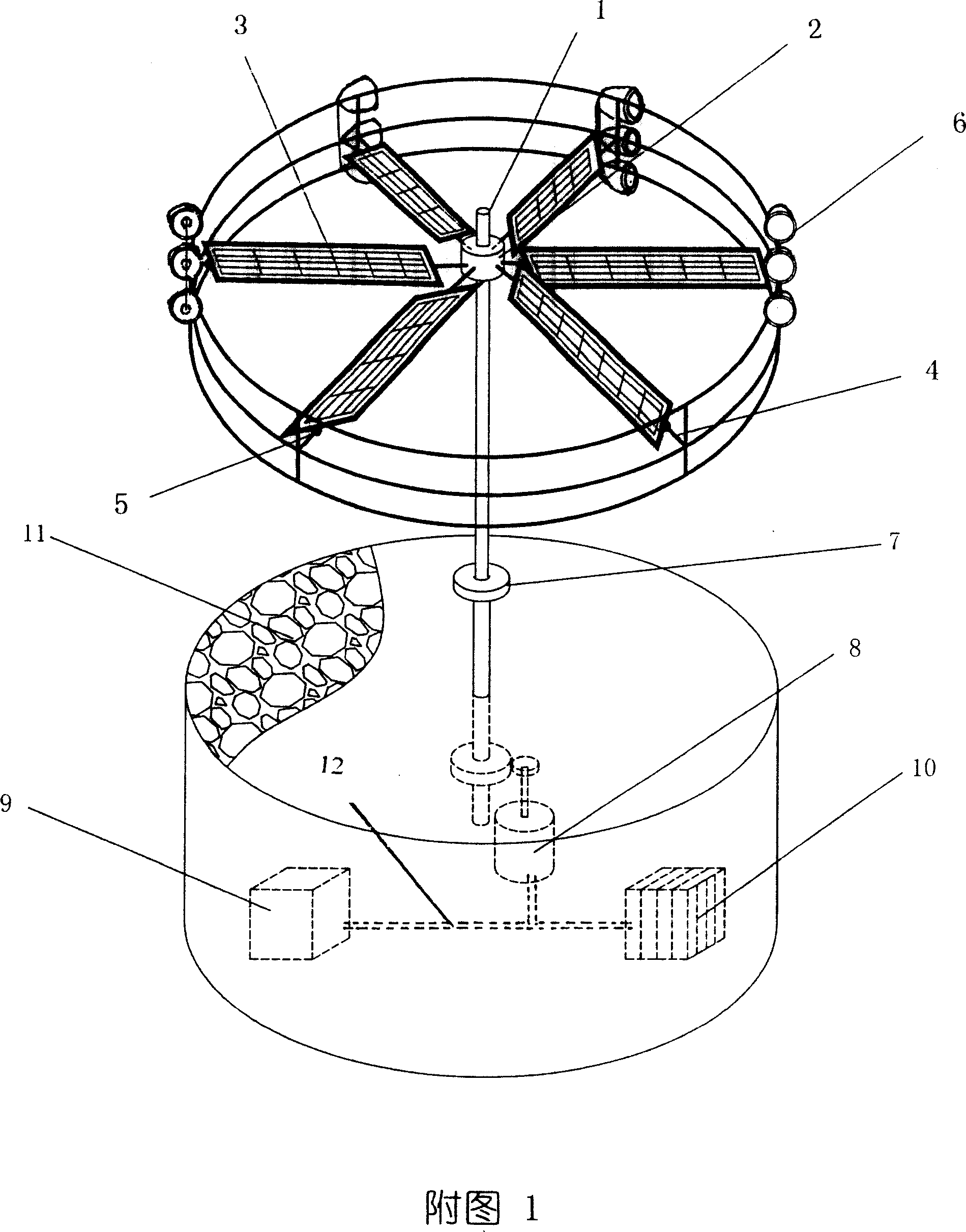
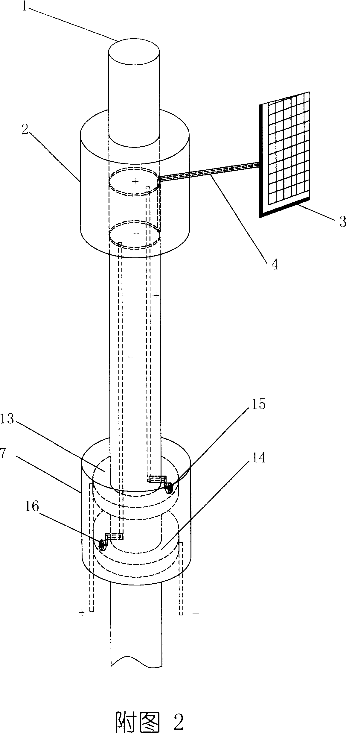
[0018] Embodiment 1. The overall structure of the advection wind-solar composite power generation device and the structure of wind energy and light energy in this embodiment are shown in Figure 1 and Figure 2: Wind power generation structure: a vertical axis horizontal wind flow rectangular blade radiation distribution structure, including There are: a hollow tubular fixed main shaft 1, a spoke beam and a spoke ring beam frame structure 2 located on the upper part of the main shaft, 6 paddle frame wind-raising components 3 with solar cells on the upper and lower sides installed on the 6 radially symmetrically distributed spoke beams, The rotating shaft 4 installed on the spoke beam to adjust the angle of the blade frame, the positioning fastener 5 to fix the angle of the blade frame, and 6 groups of 18 wind cup-shaped wind-repelling members 6 ( Only schematically draw 4 groups in accompanying drawing 1), the mechanical variable speed structure that is connected with the main sh...

Embodiment 2

[0021] Embodiment 2. The overall structure of the advection wind-solar composite power generation device and the structure of wind energy and light energy in this embodiment are basically the same as in Embodiment 1: wind power generation structure: a structure composed of vertical axis horizontal wind flow propeller blade radiation distribution, including: hollow tubular fixed main shaft , the spoke wheel spoke beam and the spoke ring beam frame structure located on the upper part of the main shaft, 18 spiral blade frame wind-raising components with solar cells on the upper and lower sides installed on the 18 radially symmetrically distributed spoke beams, and the adjusting paddles installed on the spoke beams The rotating shaft for the angle of the blade frame, the positioning fasteners for fixing the angle of the blade frame, 18 groups of 64 air bucket-shaped wind-repelling components installed on the periphery of the radially symmetrical distribution, the mechanical speed ch...


PUM


Abstract

The invention relates to an advection wind light composite generator and relative application. The invention is characterized in that the generator is vertical axle advection rectangle type or screw blade radiation distributing type, to rotate the main axle via wind rejecter and wind lifter, to operate mechanical speed changer and generation converter to generate electricity via wind. The light generator is dynamic-static battery template incline adjustable photoelectric converter, via solar battery template on beam rectangle or upper and lower faces of screw blade and the reflection of reflective membrane on ground to receive light radiation, to select right incline angle of battery membrane relative to the wind lifting and rejecting via rotation axle and angle fixing element. The invention can realize photoelectric conversion and dynamic-static transmission.

Description

technical field [0001] The present invention relates to the field of energy technology, to be precise, to the technical field of wind power generation and solar power generation. Background technique [0002] Energy technology is the basic technology for the operation and development of the world economy and society. Especially in the post-petroleum era, how to efficiently develop and utilize natural energy technology is a major issue in the current energy strategy of the international community. Using wind energy to generate electricity through mechanical energy conversion, and using solar energy to generate electricity through photoelectric conversion are relatively mature and widely used natural renewable energy utilization technologies, but these two types of technologies also have their own shortcomings and defects. Wind or windy weather and geographical conditions just can not run, and solar power generation is also difficult to work at night and cloudy time and weathe...

Claims


Application Information

Patent Timeline
Patent Type & Authority Applications(China)
IPC IPC(8): F03D9/00H02J7/14H02N6/00F03D9/25H02S10/12H02S20/32H02S40/22
CPCY02E10/46Y02E10/72Y02E10/50
Inventor 马元威
Owner 马元威
Why Eureka
Try Eureka