Light guide plate, mold for forming light guide plate, and method for manufacturing a mold for forming light guide plate
A manufacturing method and technology of light guide plates, applied in the direction of manufacturing tools, optics, light guides, etc., can solve the problems of stable improvement and difficult output efficiency
Inactive Publication Date: 2007-08-15
SEIKO EPSON CORP
View PDF1 Cites 22 Cited by
- Summary
- Abstract
- Description
- Claims
- Application Information
AI Technical Summary
Problems solved by technology
[0008] However, in the mold for forming a light guide plate manufactured by the conventional manufacturing method described in the above-mentioned Patent Document 1, since a part of the area other than the inner surface of the recess on the processed surface is mirror-finished
Method used
View moreImage
Smart ImageViewing Examples
Examples
 PUM
| Property | Measurement | Unit |
|---|---|---|
| Depth | aaaaa | aaaaa |
| Surface roughness | aaaaa | aaaaa |
Abstract
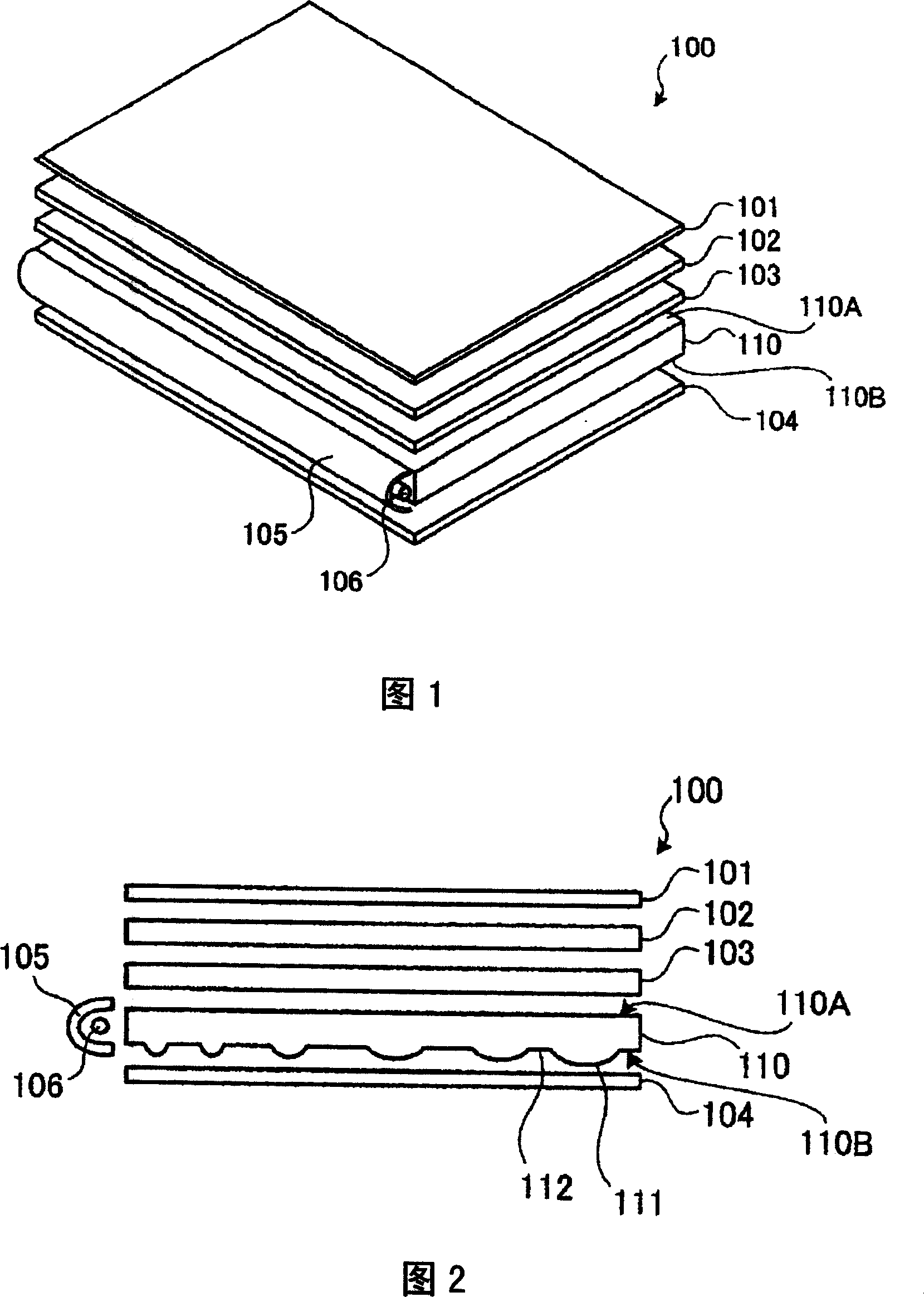
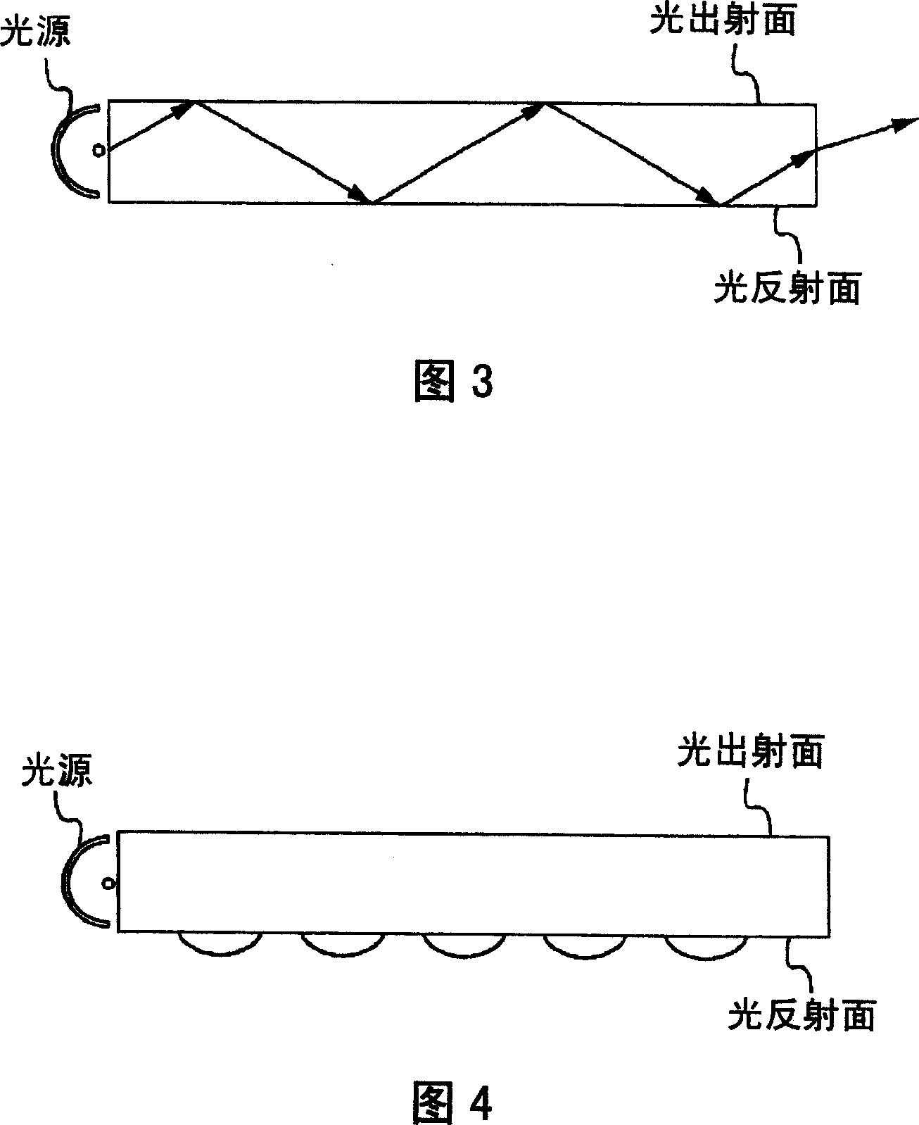
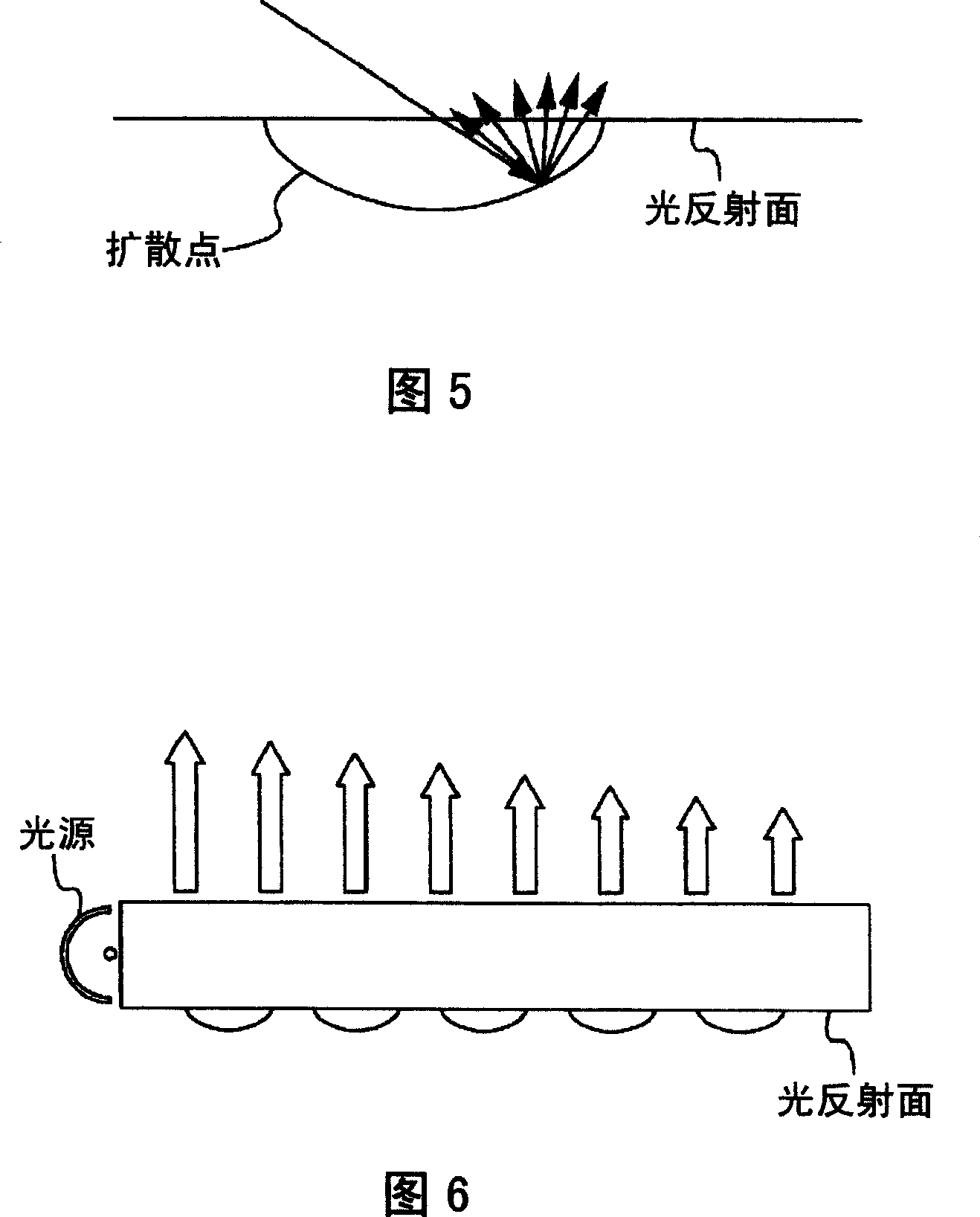
The invention provides a light guide plate, a forming model of the light guide plate, and its produce method. The light guide plate comprises: light outgoing plane incidence from side surface and outgoing light, and light reflex plane reflexing the light. The light guide plate characters in that at least one of the light outgoing plane and the light reflex plane comprises: plenty of first light diffusion parts, which are concavity or convexity in the thickness direction of the light guide plate, and diffuse the light; second light diffusion parts, which are located among the light diffusion parts, and have the same surface roughness. The light guide plate stably improve light outgoing efficiency.
Description
technical field [0001] The present invention relates to an illuminating device that can be used in various display devices such as liquid crystal display devices, and light from a light source is incident from the side, and is equipped with a light exit surface for emitting the light and a light reflector for reflecting the light. A surface light guide plate, a mold for forming a light guide plate, a method for manufacturing a mold for forming a light guide plate, and a method for manufacturing a light guide plate, in particular to a light guide plate capable of improving the light emission efficiency from a light source, a mold for forming a light guide plate, and a light guide plate. A method of manufacturing a mold for forming a light plate and a method of manufacturing a light guide plate. Background technique [0002] In recent years, various display devices, such as liquid crystal display devices, which are widely used in televisions and personal computers, have provid...
Claims
Login to View More Application Information
Patent Timeline
 IPC IPC(8): G02B6/00B24B13/00G02F1/1335
Inventor 横田启
Owner SEIKO EPSON CORP
Features
- R&D
- Intellectual Property
- Life Sciences
- Materials
- Tech Scout
- Unparalleled Data Quality
- Higher Quality Content
- 60% Fewer Hallucinations
Learn More Browse by: Latest US Patents, China's latest patents, Technical Efficacy Thesaurus, Application Domain, Technology Topic, Popular Technical Reports.
© 2025 PatSnap. All rights reserved.Legal|Privacy policy|Modern Slavery Act Transparency Statement|Sitemap|About US| Contact US: help@patsnap.com


