Connector

A connector and riveting technology, which is applied in the direction of connection, two-part connection device, parts of connection device, etc., can solve problems such as connector enlargement and solder cracking

Inactive Publication Date: 2007-08-15
HIROSE ELECTRIC GROUP
View PDF1 Cites 5 Cited by
  • Summary
  • Abstract
  • Description
  • Claims
  • Application Information

AI Technical Summary

Problems solved by technology

[0004] In this conventional structure, since the width "K" of the strip body 115 in the insertion/extraction direction "E" of the opposite connector is set to be smaller than the width "L" of the concave portion 124 in the same direction, even if the strip body 115 is folded into the After the concave portion 124, a gap “M” will also be generated between the strip body 115 an

Method used


Image

  • Connector
  • Connector
  • Connector

Examples


Example Embodiment

[0037] Hereinafter, an embodiment of the electrical connector of the present invention will be described with reference to the drawings.

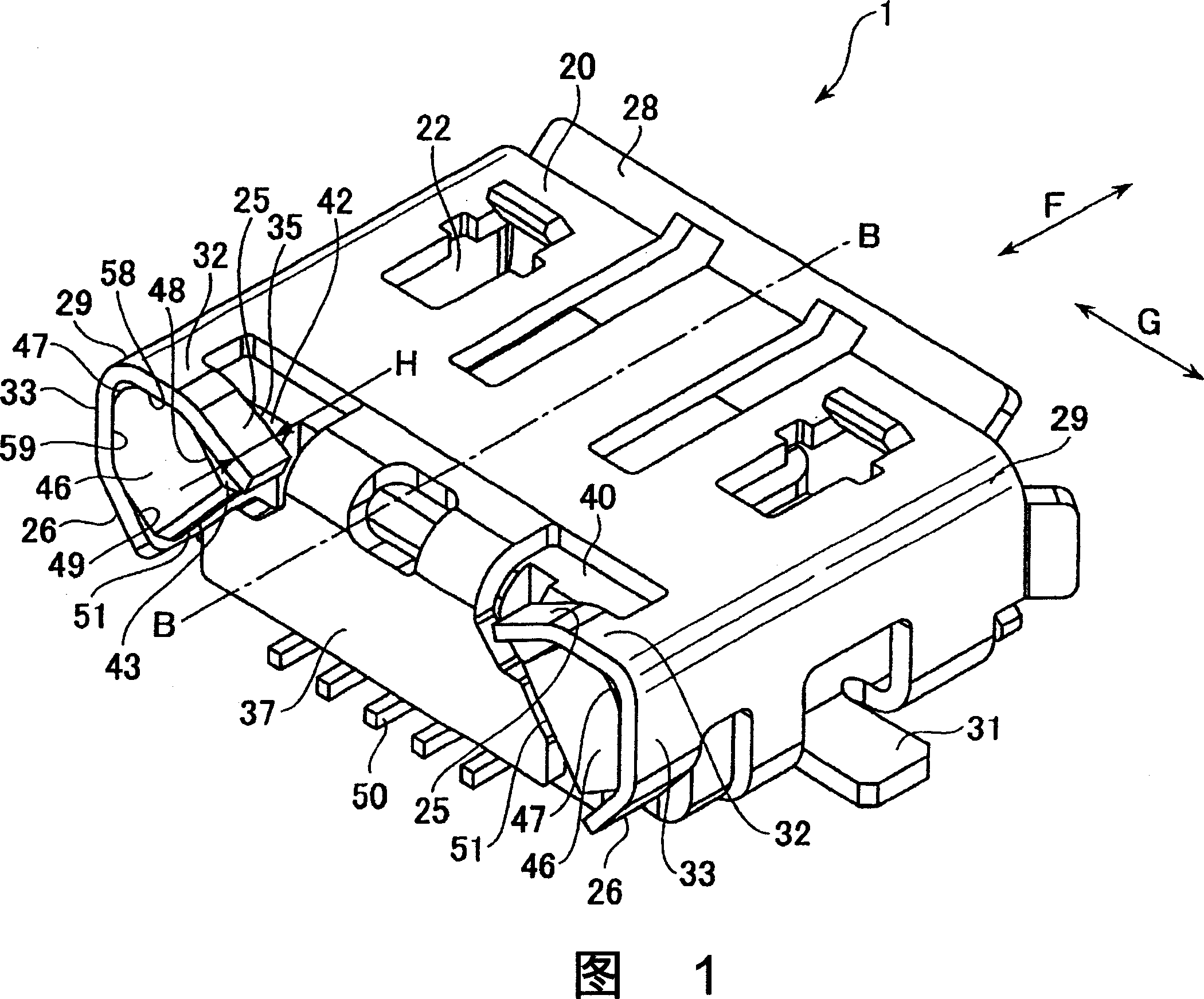
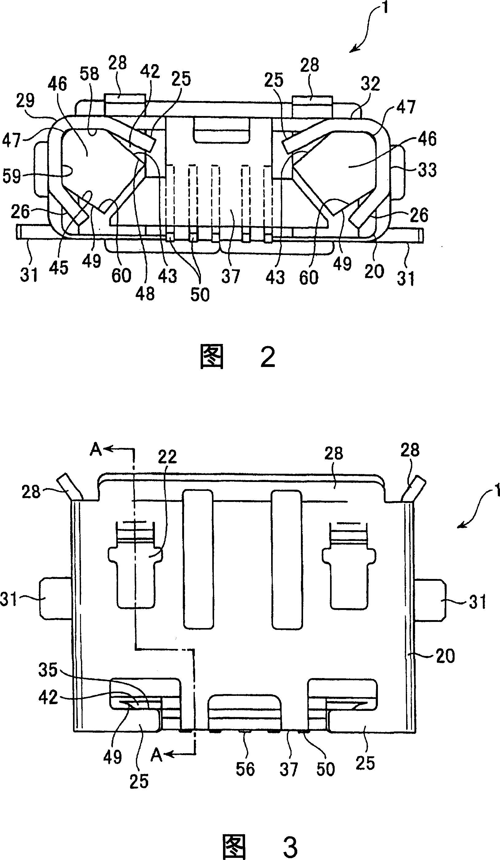
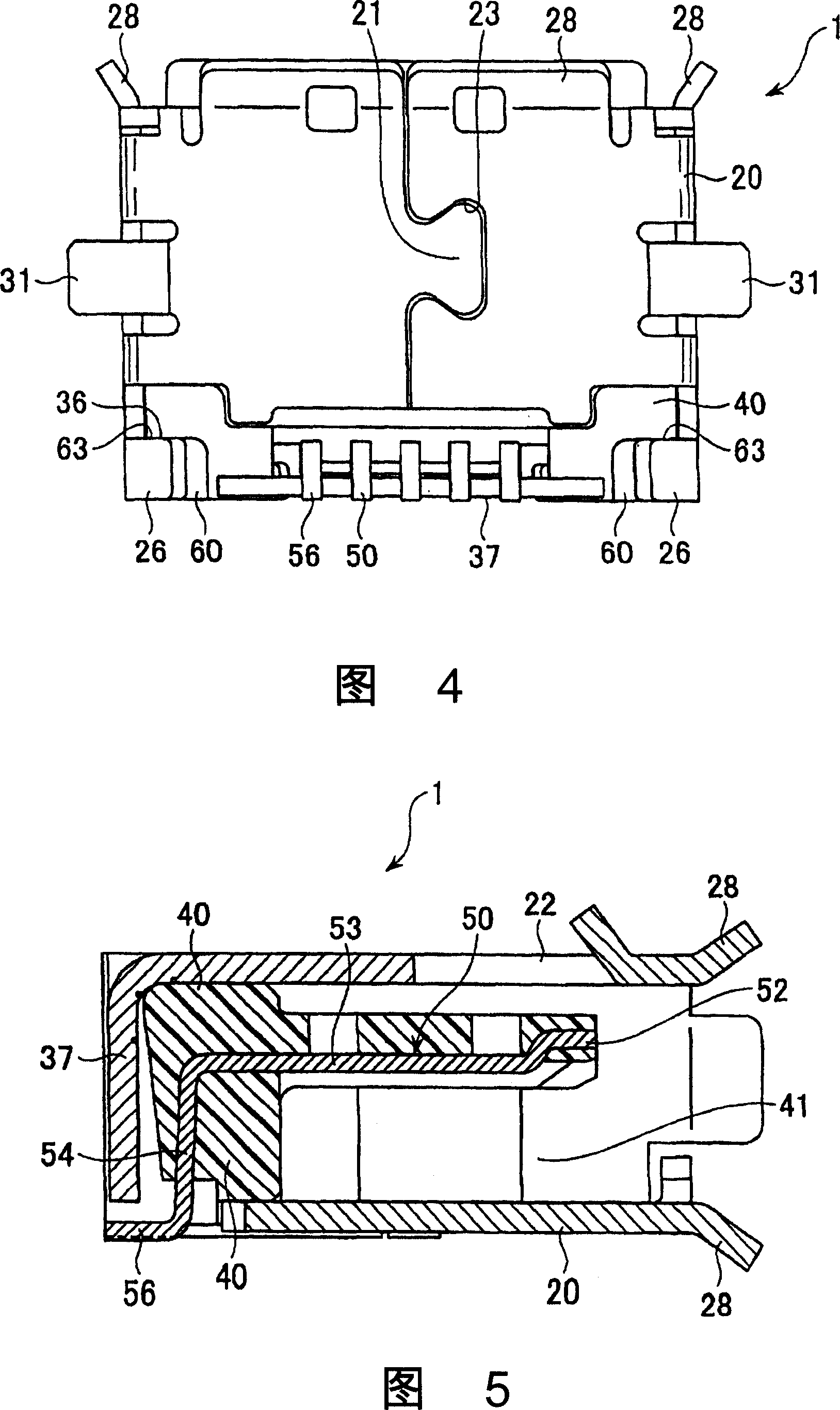
[0038] Fig. 1 is a rear perspective view of the electrical connector 1 of the present invention, Fig. 2 is a rear view, Fig. 3 is a top view, Fig. 4 is a bottom view, Fig. 5 is a cross-sectional view taken along line AA of Fig. 3, and Fig. 6 is a connection with the other side A cross-sectional view of the center line when the device is fitted. The electrical connector 1 is used as a so-called socket-side connector 1. As shown in FIG. 6, when actually used, it is made into a state of being fixed to a substrate, for example, and the plug-side connector (mating connector) 80 can be installed in the connector. 1 is free to plug and unplug.

[0039] The electrical connector 1 has: a housing 40 formed of resin; a metal shell cover (Shell) 20 covering the outside of the housing 40; and terminals 50 arranged in parallel in the housing 40 at a narrow p...


PUM


Abstract

A connector includes a housing, a housing cover for covering at least part of the housing, and a plurality of terminals arranged in the housing. The housing cover has a tongue portion extending in a direction perpendicular to the plugging direction. The side edge of the tongue portion is brought into close contact with the housing by means of cutting by the tongue portion. The invention provides a method of forcely riveting the housing cover such metal housing to the housing, in order to enforce the fastness between them.

Description

technical field [0001] The present invention relates to a connector provided with a housing cover, and more specifically, to a connector in which a part of the housing cover can be embedded in a housing. Background technique [0002] 7 and 8 show a conventional example of a connector 100 provided with a housing cover disclosed in JP-A-7-220814. FIG. 7 is a plan view of the connector shown in this publication, and FIG. 8 is a rear view thereof. [0003] The connector 100 is composed of a housing 121 , a metal cover 110 covering a part of the housing 121 , and a joint 130 fixed to the housing 121 . As shown in FIG. 8 , the metal cover 110 is fixed to the housing 121 by folding the strip body 115 of the metal cover 110 into the concave portion 124 of the housing 121 and pressing it downward. [0004] In this conventional structure, since the width "K" of the strip body 115 in the insertion / extraction direction "E" of the opposite connector is set to be smaller than the width ...

Claims


Application Information

Patent Timeline
IPC IPC(8): H01R13/46H01R24/00H01R13/648
CPCH01R13/6582H01R23/6873H01R13/639
Inventor 小山良三若月英二
Owner HIROSE ELECTRIC GROUP
Why Eureka
Try Eureka