Crankshaft forging die

A technology for molds and crankshafts, applied in the direction of manufacturing tools, forging/pressing/hammer devices, forging/pressing/hammering machinery, etc., can solve the problems of high production costs, low material and energy utilization rates, etc.

Inactive Publication Date: 2007-08-22
CHONGQING UNIV
View PDF0 Cites 26 Cited by
  • Summary
  • Abstract
  • Description
  • Claims
  • Application Information

AI Technical Summary

Problems solved by technology

The low utilization rate of materials and energy and high production cost are the ...

Method used


Image

  • Crankshaft forging die
  • Crankshaft forging die

Examples


Embodiment 1

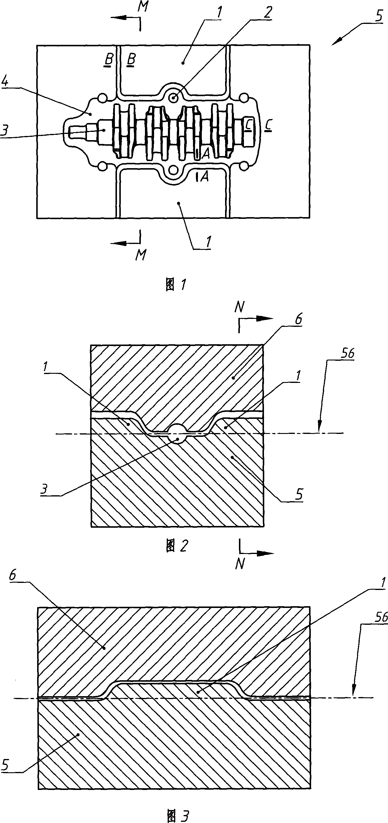
[0013] Embodiment 1 (with reference to Fig. 1,2,3,4):

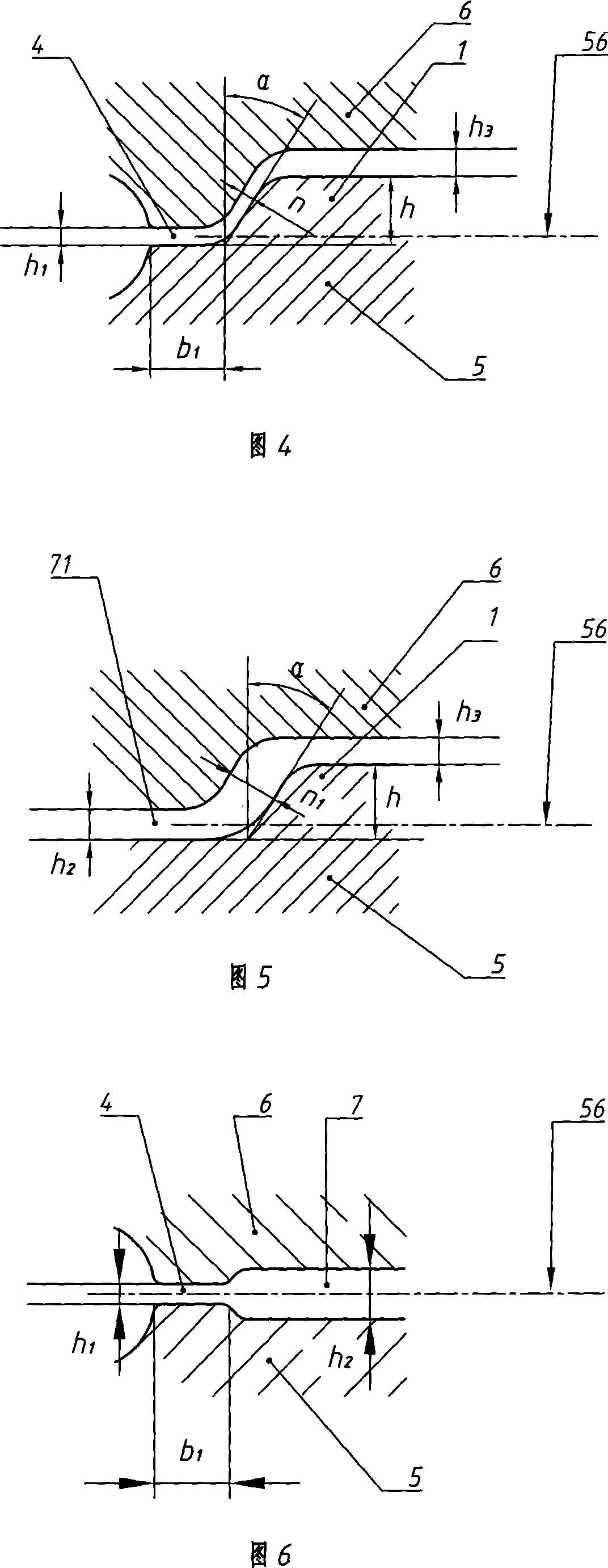
[0014] A die for forging a crankshaft. At the parting surface 56 of the upper and lower molds of the mold, a flash groove formed by a flash bridge 4 and a flash bin 7 surrounding the outer periphery of the flash bridge 4 is provided along the periphery of the cavity 3 of the mold. . In the flash groove of the present invention, corresponding to the original flash warehouse part 7 on both sides of the cavity part of the crankshaft balance weight, the wall body 1 exceeding its parting surface 56 is provided on one side of the lower die 5 (obviously, when necessary , the wall 1 needs to give way to the forging die ejector pin hole 2); between the protruding wall 1 and the concave part of the corresponding original flash warehouse part 7 in the upper mold 6, there is a width and a flash The height of the bridge portion 4 corresponds to the gap h3. That is to say, at the original flash bin portion 7 on both sides of the mol...

Embodiment 2

[0022] A die for forging a crankshaft. At the parting surface 56 of the upper and lower molds of the mold, a flash groove formed by a flash bridge 4 and a flash bin 7 surrounding the outer periphery of the flash bridge 4 is provided along the periphery of the cavity 3 of the mold. . In the flash groove of the present invention, at the original flash warehouse part 7 on both sides of the mold cavity part corresponding to the crankshaft balance weight, the wall body 1 exceeding its parting surface 56 is provided on one side of the upper mold 6 (obviously, in If necessary, the body of wall 1 needs to make way for the forging die ejector pin hole 2); between the protruding body of wall 1 and the concave part at the corresponding original flash bin part 7 in the lower die 5, there is a width and There is a gap corresponding to the width of the flash bridge portion 4 .

[0023] Apparently, the difference between this embodiment and the embodiment only lies in that the resistance w...


PUM

PropertyMeasurementUnit
Heightaaaaaaaaaa

Abstract

The crankshaft forging die has one flash gutter comprising one flash bridge and one flash bin set around the die cavity and in the die joint between the upper die and the lower die. Inside the flash gutter, one raised wall beyond the die joint is set in one side of the upper die or the lower die and in the location corresponding to the flash bin of die cavity for the crankshaft balancing block. Compared with available technology, the wall structure alters the metal flow direction and increases the horizontal flow resistance, and this results in the possibility of adopting relatively small size blank, raised material utilization rate and lowered energy source consumption.

Description

technical field [0001] The invention relates to die forging in the field of forging, in particular to a die for forging a crankshaft. Background technique [0002] In the mold of the crankshaft forging process, according to the traditional method, a flash groove composed of a flash bridge part and a flash chamber part is arranged along the periphery of the die cavity at the parting surface of the upper and lower dies of the die. The flash bridge is a gap surface directly connected to the die cavity in the flash groove. The gap surface is composed of a shallow concave surface corresponding to the upper and lower dies. The excess metal is extruded through the gap surface to form a flash edge. Resistance can be generated to fill the cavity with metal. The flash chamber part is a groove around the outer periphery of the flash bridge, which is composed of a deep concave surface at the corresponding position of the upper and lower dies, which is used to accommodate excess metal m...

Claims


Application Information

Patent Timeline
IPC IPC(8): B21J13/02B21K1/08
Inventor 周杰刘敏夏玉峰权国政
Owner CHONGQING UNIV
Why Eureka
Try Eureka