Distortion compensating amplifier apparatus

A distortion compensation and amplification device technology, which is applied to the parts of the amplification device, amplifiers, power amplifiers, etc., can solve the problems of small distortion output and reduced accuracy of compensation value, and achieve the effect of fast convergence speed

Inactive Publication Date: 2007-08-22
ITACHI KOKUSAI ELECTRIC INC
View PDF6 Cites 11 Cited by
  • Summary
  • Abstract
  • Description
  • Claims
  • Application Information

AI Technical Summary

Problems solved by technology

That is, since the distortion output is small when the input signal level is small, when updating the compensation value corresponding to a large input level, if the update process is performed using the distortion corresponding to an arbitrary input level, it will take a long time to make the compensation value value becomes the correct value, and the accuracy of the compensation value of the table is also reduced

Method used


Image

  • Distortion compensating amplifier apparatus
  • Distortion compensating amplifier apparatus
  • Distortion compensating amplifier apparatus

Examples


Embodiment 1

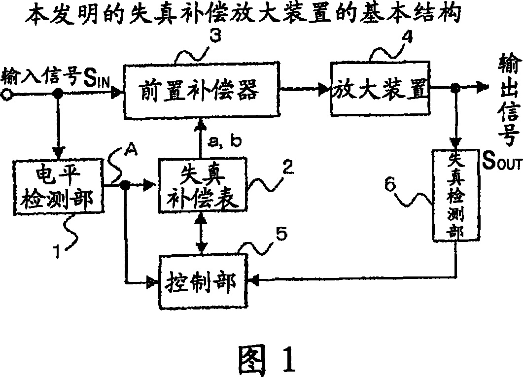
[0052] FIG. 5 is a block diagram showing the basic configuration of the distortion compensation amplifier of the first embodiment. The distortion compensating amplifying device of this example is clearly shown to include a threshold detection unit 17 which detects that the signal level has exceeded a threshold and determines the timing of obtaining the feedback signal, a memory 16 which stores the feedback signal, and the like.

[0053] In addition, as described in the description of FIG. 3, the frequency converter or the A / D, D The installation and structure of the / A converter are not related to the essence of this example and can be applied in any case, so only the basic components are shown.

[0054] Each part of FIG. 5 is demonstrated. Components assigned the same symbols as in the description of the prior art basically have the same structure as the prior art. Hereinafter, the term “input signal” means an input signal to the distortion compensation amplifying device of...

Embodiment 2

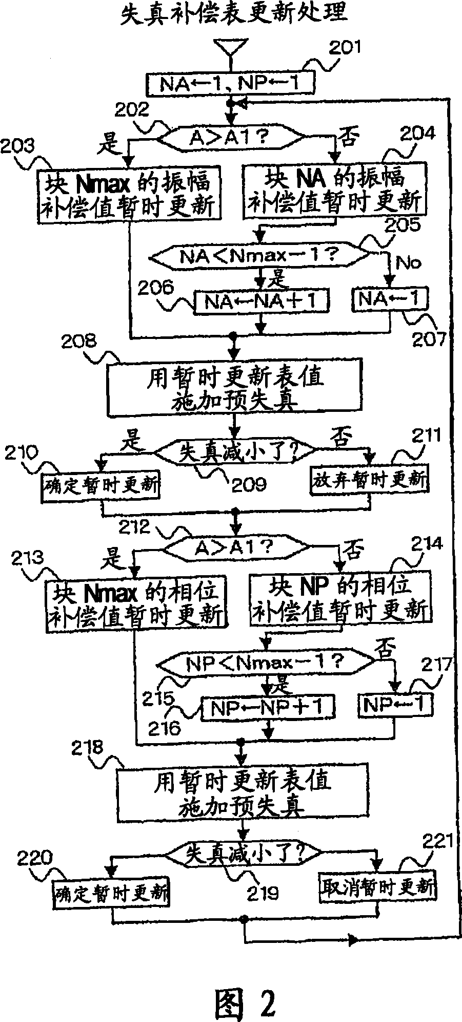
[0069] FIG. 7 is a block diagram showing the configuration of the distortion compensation amplifier of this example. Compared with the previous first embodiment, this example is different in that a level equivalent to a so-called peak value higher than the standard level during normal transmission is set as the threshold value of the threshold detection part 27, and the control part 25 utilizes FFT Aspects of evaluating the distortion and modeling the distortion of the amplification device 4 using a power function are more specific. Structures not mentioned in this embodiment are assumed to be equivalent to Embodiment 1.

[0070] input signal IN It is a digital IF signal, has a sampling frequency that uses a frequency band wider than the signal to be amplified (for example, 3 to 5 times), and is composed of I-phase and Q-phase components, so it is represented by two lines in the figure . The distortion compensation table 22 stores, in complex number form, compensation amoun...

Embodiment 3

[0080] This example is different from the previous embodiment 2 in that the threshold value is changed, and the power function is more specific. The structure not mentioned in this embodiment is assumed to be equivalent to Embodiment 1 or 2.

[0081] As a power function model, in a general so-called Mark Laurin series that expands around zero amplitude, it is not possible to appropriately represent both compensation values ​​at the time of small amplitude and the time of large amplitude. Therefore, it is described in Japanese Patent Application No. 2005-198349 that a power function that generates even-order distortion can be used like a series expanded at a point other than zero.

[0082] In this example, in order to increase the degree of freedom for the compensation value at low input levels, a power function model represented by the following equation is used.

[0083] C A ( x ) ...


PUM


Abstract

An amplifier apparatus for providing a pre-distortion to perform a distortion compensation, wherein even if the frequency of occurrence of levels around the input signal peak is small, a distortion compensation table is efficiently updated so as to improve the performance of the distortion compensation. The compensation values of a distortion compensation table (2) are divided into a first group of compensation values corresponding to large input levels that lead to large output distortions and a second group of compensation values corresponding to the other small input levels. If a level detected by a level detecting part (1) exceeds a threshold value, a control part (5) updates the first group of compensation values. Otherwise, the control part (5) updates the second group of compensation values. In this way, the updating process can be effectively performed even for signals having small frequencies of occurrence of the peak values of the signal levels as in the CDMA or OFDM system, thereby improving the performance of the distortion compensation.

Description

technical field [0001] The present invention relates to a distortion compensation amplifying device, and more particularly, to a distortion compensating amplifying device which applies distortion to an input signal by a predistorter having a characteristic opposite to that of the amplifying device, and inputs the output to the amplifying device. Background technique [0002] In a mobile communication system employing, for example, W-CDMA (Wide-band Code Division Multiple Access) as a mobile communication method, the base station device needs to allow wireless signals to reach physically distant mobile station devices. . Therefore, the amplifying device of the base station needs to greatly amplify the signal, and it is possible to take measures to amplify the signal used up to the range showing the nonlinear characteristic due to saturation, and to suppress the signal caused by the nonlinear characteristic, etc. resulting in distorted signals. [0003] As a method for suppr...

Claims


Application Information

Patent Timeline
Patent Type & Authority Applications(China)
IPC IPC(8): H03F1/32H03F3/24H04B1/04
CPCH03F3/24H03F1/3247H03F2201/3233H04B1/0475
Inventor 古田敏史本江直树
Owner ITACHI KOKUSAI ELECTRIC INC
Why Eureka
Try Eureka