Quasi-spherical orbital implant

An implant, orbital technology, used in eye implants, medical science, prostheses, etc., can solve the problems of tissue infection of nail implants, inability to be attached to extraocular muscles, and inability to properly assemble

Inactive Publication Date: 2007-08-29
OCULO PLASTIK
View PDF2 Cites 5 Cited by
  • Summary
  • Abstract
  • Description
  • Claims
  • Application Information

AI Technical Summary

Problems solved by technology

The problem with these devices is that they are smooth on all sides and therefore cannot be attached to extraocular muscles
The problem with non-spherical implants is that "stock" prosthetic eyes do not fit properly on

Method used


Image

  • Quasi-spherical orbital implant
  • Quasi-spherical orbital implant
  • Quasi-spherical orbital implant

Examples


Embodiment Construction

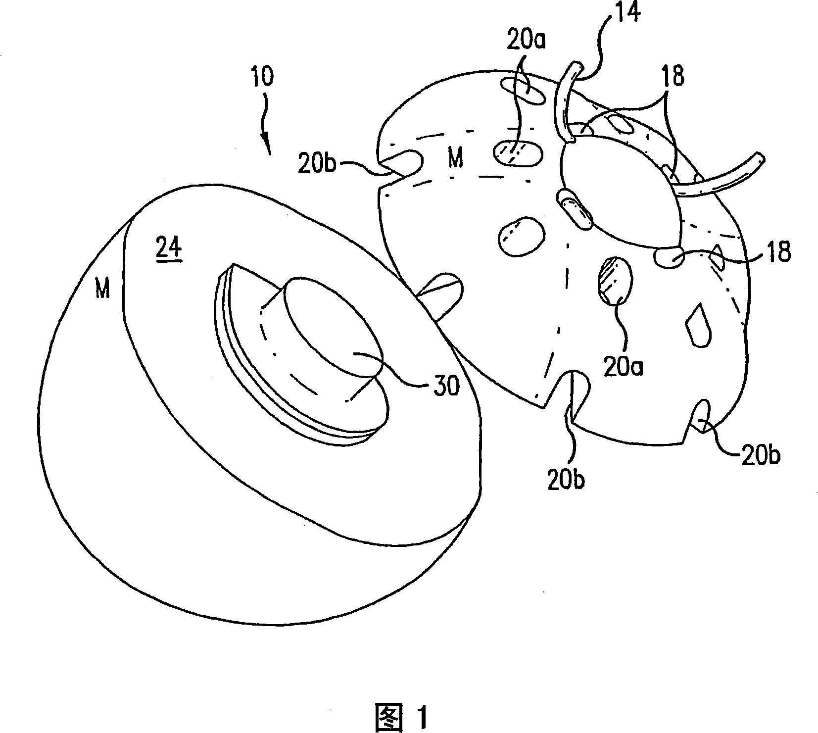
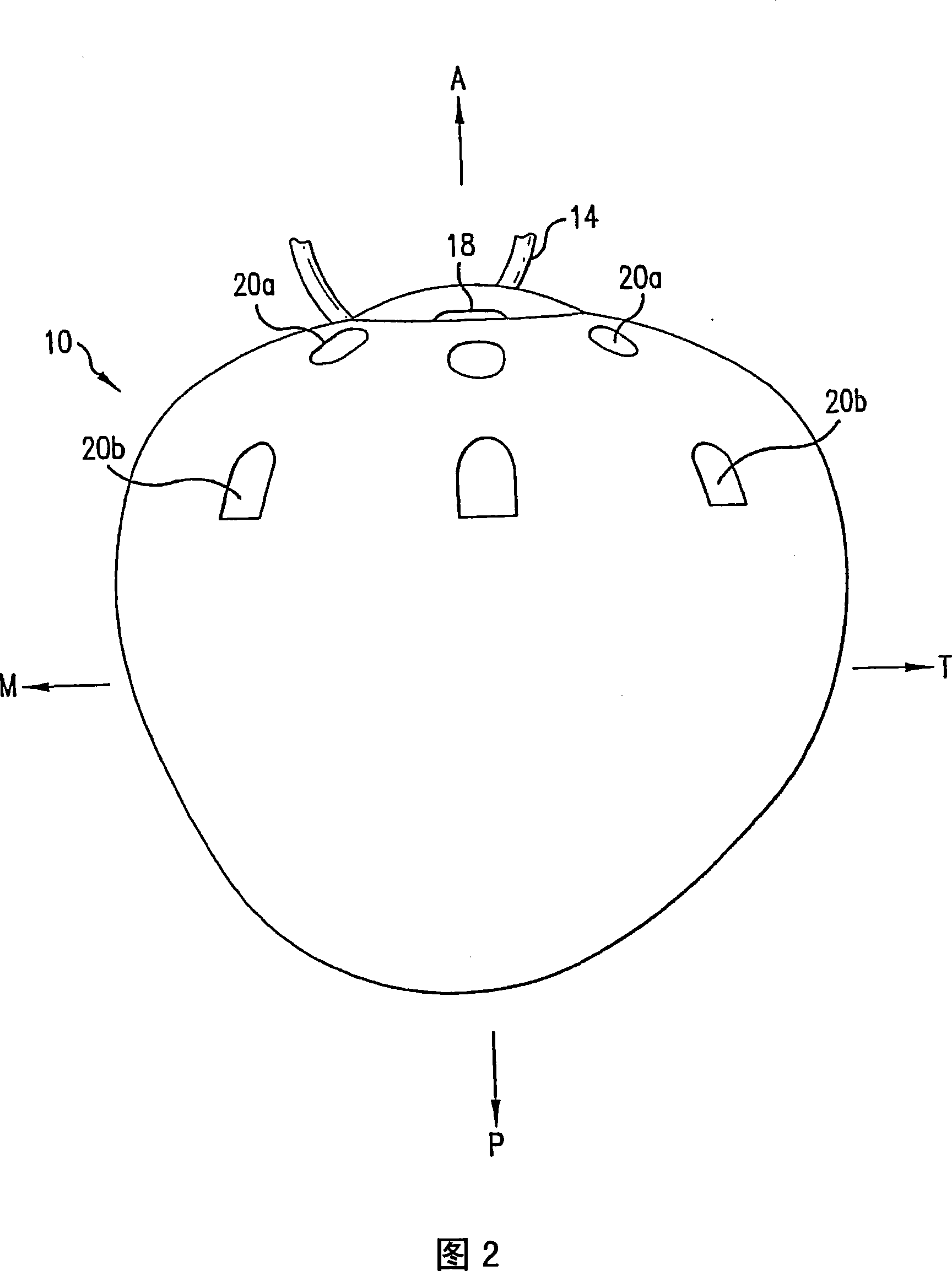
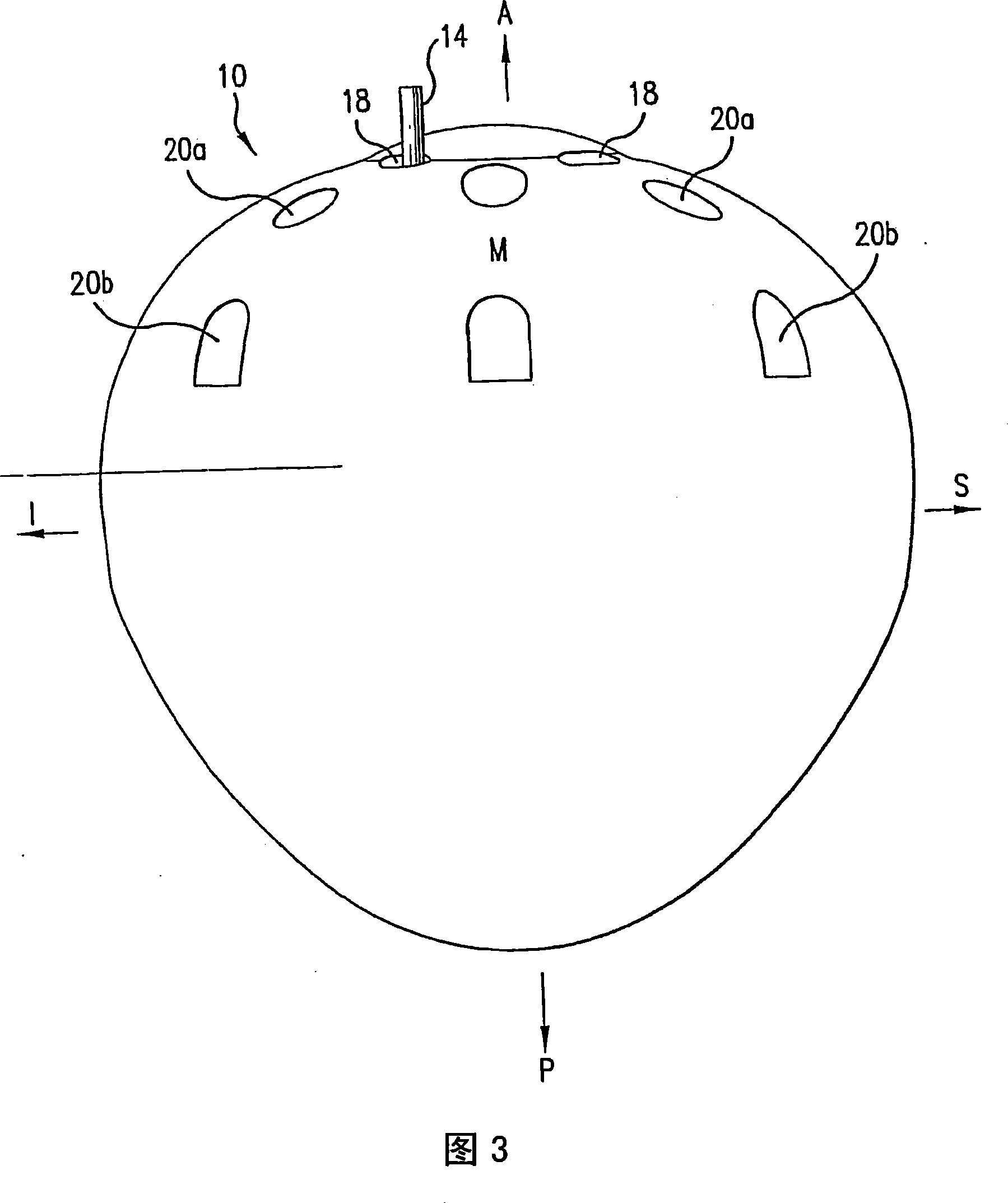
[0032] As generally seen in FIG. 1 , the ocular implant 10 of the present invention includes an anterior portion 22 and a posterior portion 24 . Although implant 10 may be fabricated as a single piece, preferred embodiments require implant 10 to be fabricated as two separate pieces. These two pieces 22 , 24 will be collectively referred to as the implant 10 . The front portion 22 includes a limited number of tunnel-like apertures 18 , flue-like apertures 20 a and 20 b , depressions 11 and elevations 12 . Cumulatively, the depressions 11 and elevations 12 are referred to here as details. It should be noted that the terms Anterior A, Posterior P, Medial M, Temporal T, Superior S, and Inferior I all describe the implant 10 as being properly positioned within the patient's right orbit with the anterior portion 22 facing outside the patient's orbit. Entry 10. Each of the above directions can be seen in FIGS. 2 and 3 . 2 is a top view of the implant 10 as it is placed in the pat...


PUM


Abstract

A quasi-spherical orbital implant that comprises an off center conical elongation toward its posterior and medial aspects. The conical elongation mimics the natural shape of an orbit. The implant comprises a number of holes and tunnels for suturing the patient's eye muscles and tissue to the implant. A number of hollow voids in the implant serve to progressively host the formation of tissue which secures the implant to the muscles and covering tissue and helps to prevent migration after the sutures have dissolved. The anterior portion of the implant has a number of details which key with the prosthetic eye and help improve its stability and motility.

Description

technical field [0001] The present invention relates to eye replacement implants. If the eye has been damaged by trauma or disease, the damaged eye may have to be removed, in which all of the eye's internal contents are removed, or enucleation, in which the entire eyeball is removed from the eye muscles After separating from the optic nerve, the entire eyeball is enucleated. Following any of these steps, the resulting space is typically filled with an orbital implant and then fitted with a prosthetic eye, much like an eye. Following enucleation or extraction of the eye, tissue heals on the implant after the implant has been inserted into the eye socket. The prosthetic eye is then placed over this tissue that has healed over the implant. When properly placed in the orbit, the orbital implant replaces some of the volume lost when the eye is enucleated and helps maintain the normal structure of the eyelids and eyebrows. When the prosthetic eye is properly matched to the other...

Claims


Application Information

Patent Timeline
IPC IPC(8): A61F2/14A61L27/14
CPCA61F2/141A61L27/14
Inventor 让-弗朗索瓦·迪内特
Owner OCULO PLASTIK
Why Eureka
Try Eureka