Low switching frequency power factor correction circuit

A circuit and frequency technology, applied in the direction of irreversible AC power input conversion to DC power output, high-efficiency power electronic conversion, climate sustainability, etc., can solve the problems of increased cost and dissipation in the power conversion chain

Inactive Publication Date: 2007-08-29
INTERNATIONAL RECTIFIER COEP
View PDF0 Cites 11 Cited by
  • Summary
  • Abstract
  • Description
  • Claims
  • Application Information

AI Technical Summary

Problems solved by technology

This low voltage supply is usually obtained through dedicated circuits (usually a flyback switching power supply fed directly from the rectified line, but sometimes a step-down switching regulator) that add additional power to the ov...

Method used


Image

  • Low switching frequency power factor correction circuit
  • Low switching frequency power factor correction circuit
  • Low switching frequency power factor correction circuit

Examples


Embodiment Construction

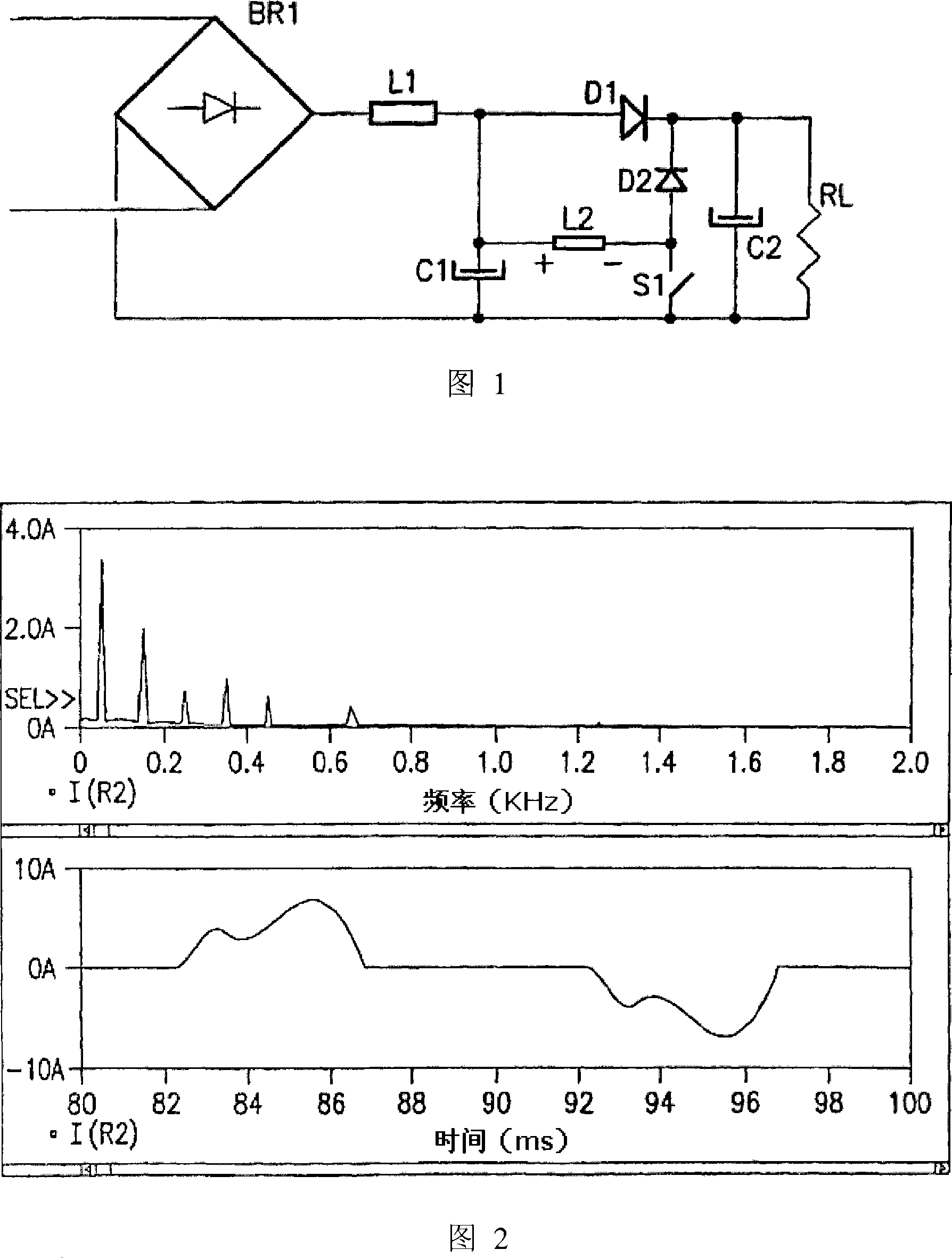
[0038] In the prior art circuit shown in Fig. 1, RL acts as an "equivalent" load of the harmonic correction (or power factor correction) circuit, representing the equipment to be fed (typically a further power conversion stage). The harmonic correction circuit consists of L1, C1, L2, S1, D1 and D2, while C2 together with BR1 represents the standard rectification and filtering stages which, when used alone, produce significant distortion of the line current. In Figure 1, the internal management power supply is not shown.

[0039] Referring to Figure 1, it is evident that the circuit in Figure 1 has several "degrees of freedom" as to how switch S1 is driven on and off in each line half-cycle.

[0040] First, the modulation of switch S1 must be the same for subsequent line half-cycles. In fact, if the modulation is different between two consecutive line half-cycles, the line current will contain a large number of even harmonics for which the specified limits are stricter than th...


PUM


Abstract

A power factor correction circuit for driving a switch of a boost type converter circuit having an AC line frequency input, comprising a sense circuit for sensing and comparing the output voltage of the boost type converter circuit to a reference voltage, a circuit responsive to the output of the sense circuit for providing a drive signal for driving the switch, wherein the drive signal comprises a pulsed signal comprising a pulse grouping during each half cycle of the AC line frequency comprising at least one pulse wherein the number of pulses and frequency of the pulses of the pulse grouping changes with the output of the sense circuit up to a threshold value with the pulse width of the pulses being substantially constant; and when the output of the sense circuit has reached the threshold value, the pulse width of the pulses of the pulse grouping are varied in accordance with the output of the sense circuit.

Description

[0001] Cross References to Related Applications [0002] This application claims U.S. Provisional Patent Application No. 60 / 642,826, filed January 11, 2005, entitled "LOW SWITCHINGFREQUENCY POWER FACTOR CORRECTION CIRCUIT," and filed December 22, 2004, entitled "LOW SWITCHINGFREQUENCY POWER FACTOR CORRECTION CIRCUIT" Priority to U.S. Provisional Patent Application No. 60 / 638,125 and U.S. Provisional Patent Application No. 60 / 578,010, filed June 7, 2004, entitled "LOWSWITCHING FREQUENCY POWER FACTOR CORRECTION CIRCUIT," the disclosure of which is incorporated by reference in its entirety combined here. Background technique [0003] The present invention relates to methods and circuits for power factor correction (PFC). PFC circuits are well known in the art and are used in a wide variety of electronic devices ranging from lighting ballast circuits to switched mode power supplies and motor drivers. [0004] Devices of this type typically require a direct current (DC) input vol...

Claims


Application Information

Patent Timeline
IPC IPC(8): H02M7/04
CPCY02B70/126
Inventor C·博基奥拉M·格拉索高桥敏男
Owner INTERNATIONAL RECTIFIER COEP
Why Eureka
Try Eureka