Electric window curtain

A technology for electric curtains and curtains, which is applied to window decorations, curtain hanging devices, household appliances, etc., and can solve the problems that two curtains cannot be opened and closed independently, increase costs, and cannot be automatically clutched at will.

Inactive Publication Date: 2007-09-05
李岱峰
View PDF0 Cites 11 Cited by
  • Summary
  • Abstract
  • Description
  • Claims
  • Application Information

AI Technical Summary

Problems solved by technology

[0004] The known movable parts and curtains are directly or indirectly fixed, and cannot be automatically clutched at will. This reason causes a set of reducer and transmission device to drive only

Method used


Image

  • Electric window curtain
  • Electric window curtain
  • Electric window curtain

Examples


Embodiment Construction

[0083] The present invention is described in detail below with reference to accompanying drawing and example,

[0084] The embodiment of monorail is the simplest, and the most popular electric curtain with square tube guide rail structure with T-shaped grooves on both sides is copied. As mentioned above, a tractor is added, that is, the position of the original pulley is replaced by a tractor. Fixed with the flat transmission belt with toothed holes, the tackle is replaced by the aforementioned tackle with movable pin, and the tripping device is fixed on the guide rail. The detailed structure can refer to the embodiment of the double track described later.

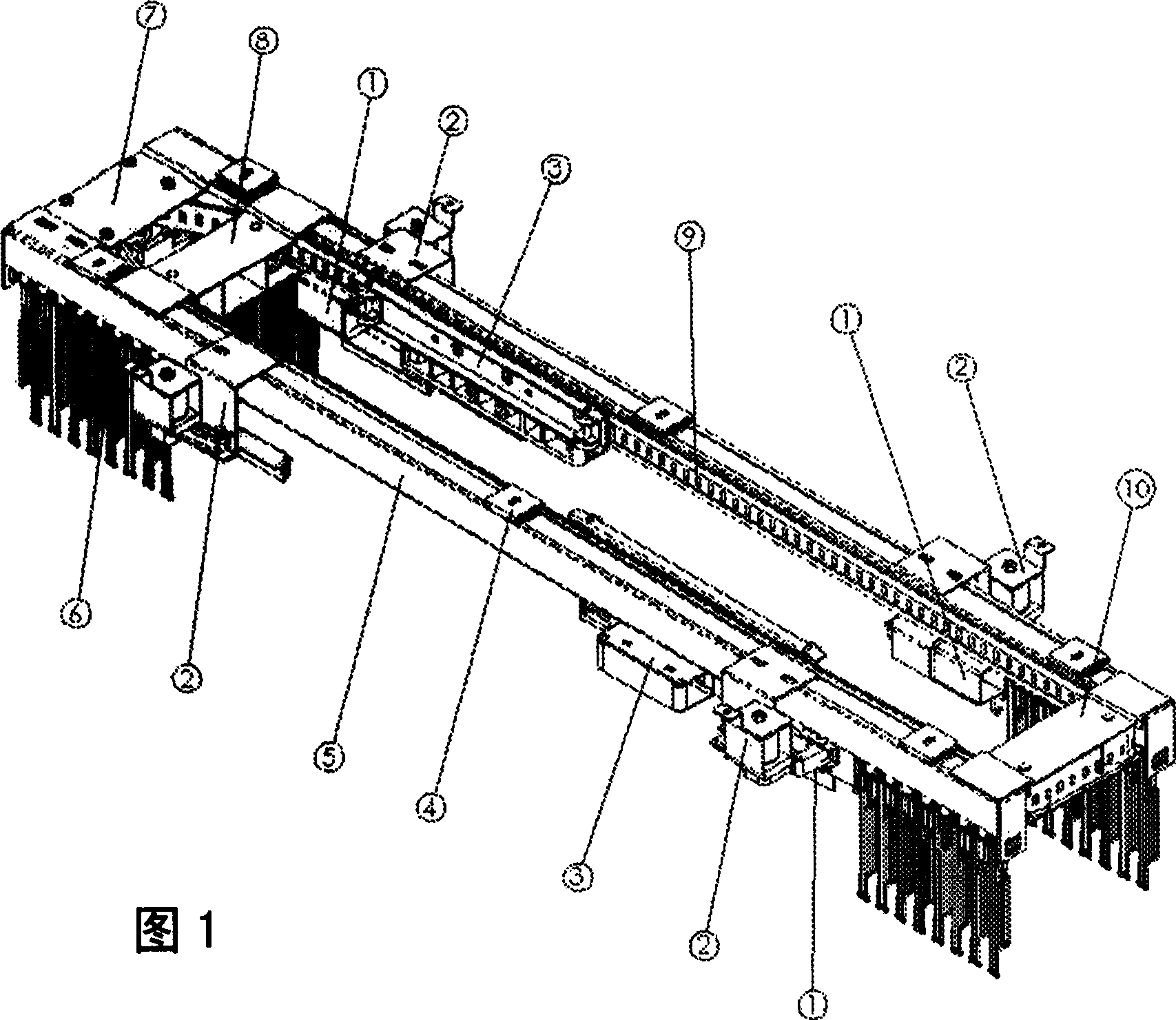
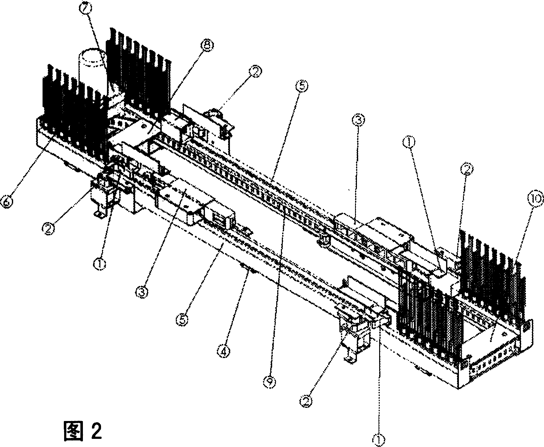
[0085] Referring to Fig. 1, Fig. 2, Fig. 1 is the axonometric perspective view of the dual-rail embodiment designed by the present invention, and Fig. 2 is the axonometric perspective view of Fig. 1 example turning over, can find out the overall structural layout of the present invention among the figure.

[0086] The redu...


PUM


Abstract

An electric window curtain is composed of a guide track set, an electric driver for driving at least one movable part of transmission unit in order to control at least one curtain, at least one carriage, a hanger unit, additional pulling carriage fixed to said movable part, and a tripping unit fixed to guide track and with stop block, locating block and pulse electromagnet.

Description

Technical field: [0001] The invention relates to the improvement of electric curtains. Background technique: [0002] Known electric curtain at least has guide rail, electric driving device, tackle, suspension device. The trolley and the hanging device are constrained by the guide rail and move along the guide rail. The trolley hangs the front edge of the curtain, and the hanging device hangs the curtain. The electric drive device is usually a motor accelerator or a linear motor, and the motor drives the transmission device after being decelerated by the reducer. , There are many transmission methods, but usually there is at least one movable part that is not necessarily bound by the guide rail but moves along the guide rail. The movable part can be the nut in the screw nut drive, the transmission belt in the belt drive, and the moving iron core in the linear motor. , motors and reducers that use friction or gear racks to move on guide rails, etc., can define movable parts ...

Claims


Application Information

Patent Timeline
IPC IPC(8): A47H5/02A47H1/04
Inventor 李岱峰李烨
Owner 李岱峰
Why Eureka
Try Eureka