Tube expanding device

一种辊子、框架的技术,应用在扩管装置领域,能够解决操作者负担大、连接部松动、振摆旋转等问题,达到缩短扩管时间、减轻负担、提高作业效率的效果

Inactive Publication Date: 2007-09-05
SUGINO MACHINE
View PDF3 Cites 16 Cited by
  • Summary
  • Abstract
  • Description
  • Claims
  • Application Information

AI Technical Summary

Problems solved by technology

Furthermore, there may be looseness in this connection part, which may cause wobbling and rotation.
[0020] In addition, since the operation of pressing the mandrel 123 against the roller 124 and separating the mandrel 123 from the roller 124 is performed manually, the burden on the operator is large.

Method used


Image

  • Tube expanding device
  • Tube expanding device
  • Tube expanding device

Examples


Embodiment Construction

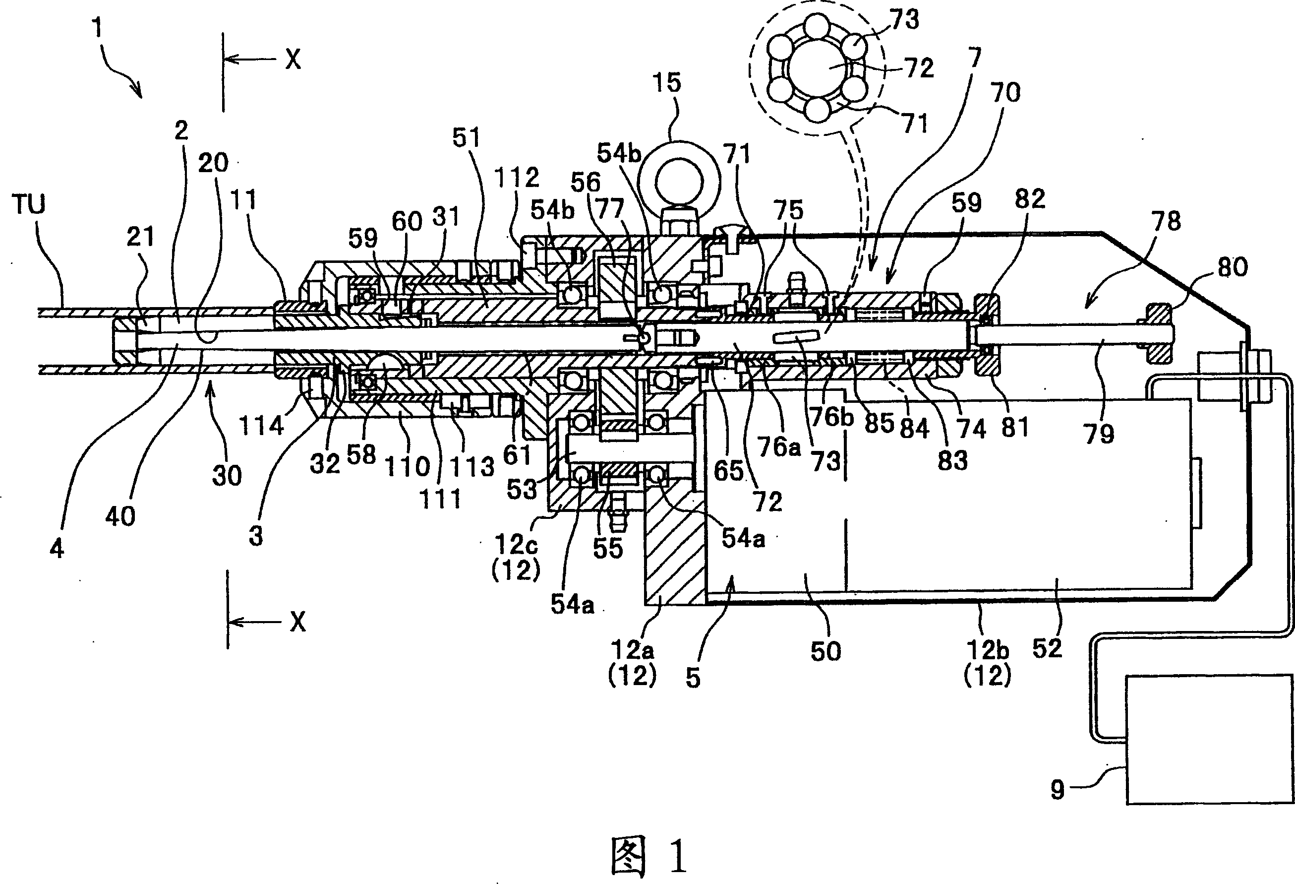
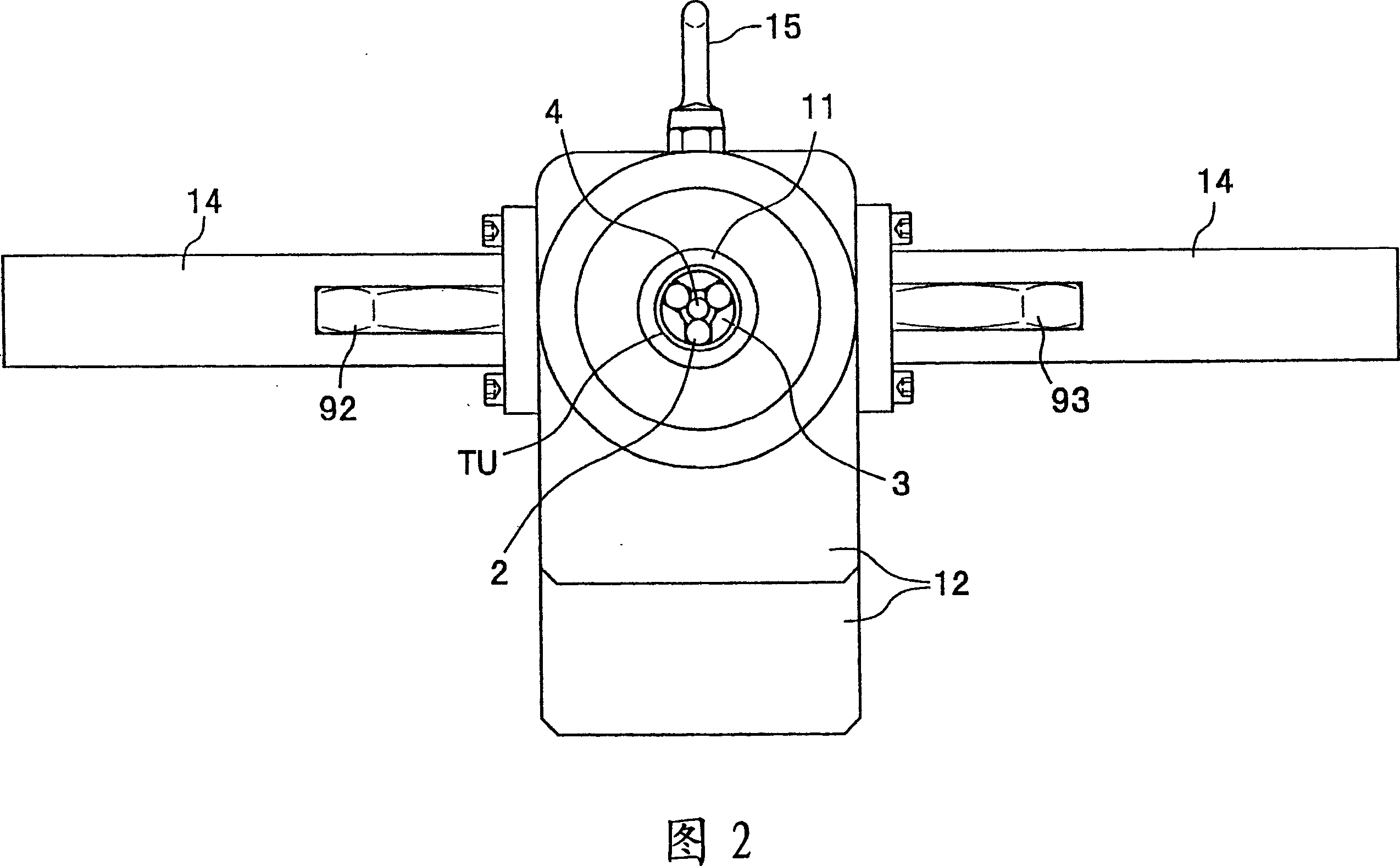
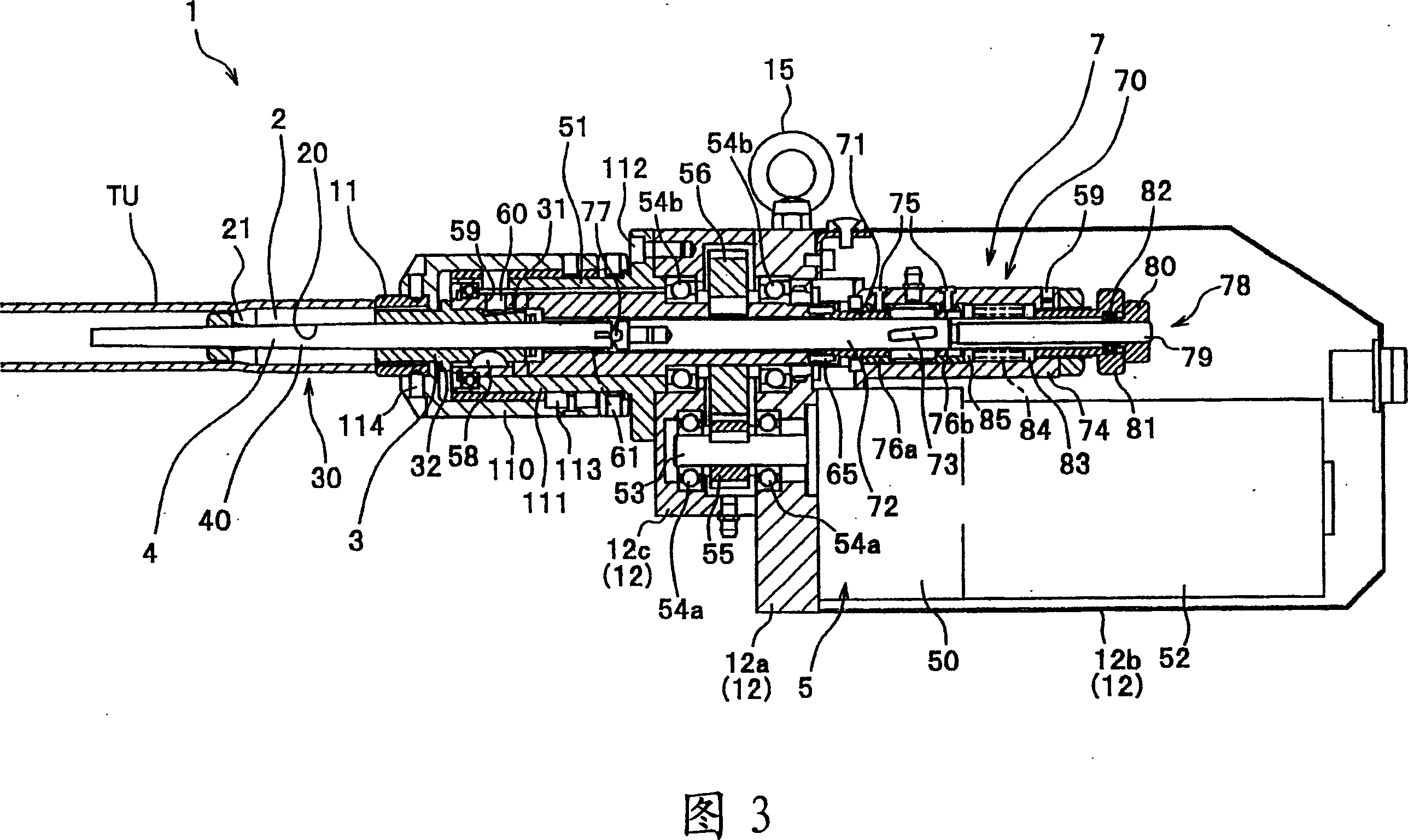
[0062] Hereinafter, the best mode for carrying out the present invention will be described in detail with reference to the drawings.

[0063] Fig. 1 is a sectional view showing the best mode of the pipe expanding device for implementing the present invention, Fig. 2 is a front view showing the best mode of the pipe expanding device for implementing the present invention, and Fig. 3 is a diagram showing the embodiment of the present invention. 4 is a cross-sectional view taken along line X-X in FIG. 1 , and FIG. 5 is a configuration diagram showing a control member of the pipe expanding device according to this embodiment.

[0064] In this embodiment, the distal end side (left side in FIG. 1 ) of the expansion frame inserted into the tube as the member to be expanded is defined as the front side, and the base end side (right side in FIG. 1 ) is defined as the rear side. , for illustration.

[0065] As shown in FIG. 1 , the pipe expanding device 1 of this embodiment includes: a...


PUM


Abstract

The present invention provides a pipe expander, which can improve the operating efficiency, shorten pipe expansion time, alleviate the workload on the operator, and facilitate highly accurate expansion operation. The pipe expander comprises: a plurality of rollers, with front end in large-diameter cone shape; a tubular expansion frame, which holds the rollers on a concentric circle freely; a spindle, which can slide and rotate freely into the expansion frame, with front end in small-diameter cone shape, to match the shape of the conical part of the rollers. As the spindle moves forward relatively to the expansion frame, the conical part of the spindle props the conical part of the rollers, so that the expansion diameter defined by the circum-circle formed by the rollers is expanded. The expander further comprises: a driving part, which is connected to the expansion frame and drives the expansion frame to rotate; a moving part, which drives the spindle to move forward or backward relatively to the expansion frame.

Description

technical field [0001] The present invention relates to a pipe expanding device for expanding and forming a pipe from the inner diameter side. Background technique [0002] Generally, in the manufacturing process of heat exchangers such as evaporators (boilers), condensers, and radiators, in the process of joining and fixing the tubes to the tube sheets, it is necessary to use a tube expanding tool to expand the tubes from the inner diameter side of the tubes. The diameter is enlarged, and the tube is fixed to the tube sheet by pressure (for example, refer to Patent Document 1 and Patent Document 2). [0003] For example, the pipe expanding tool described in Patent Document 1 is configured such that the operator connects the pipe expanding tool to a rotary drive machine, rotates the roller, and rolls the roller while pressing the inner peripheral surface of the pipe, so that it can be easily completed. Expansion work. According to this pipe expanding tool, a smooth continu...

Claims


Application Information

Patent Timeline
Patent Type & Authority Applications(China)
IPC IPC(8): B21D39/10B21D39/20B21D41/02
CPCB21D39/10B21D39/20B21D39/08B21D41/02
Inventor 铃木哲哉寺主胜之
Owner SUGINO MACHINE
Why Eureka
Try Eureka