Mineral shovel loader for lane

A technology of shovel loader and ore, which is applied in the direction of earth mover/shovel, mechanically driven excavator/dredger, construction, etc., which can solve the problems of high labor intensity, low efficiency and high risk

Inactive Publication Date: 2007-09-05
燕连根
View PDF0 Cites 8 Cited by
  • Summary
  • Abstract
  • Description
  • Claims
  • Application Information

AI Technical Summary

Problems solved by technology

[0003] The technical problem to be solved by the present invention is to provide a roadway ore shovel lo

Method used


Image

  • Mineral shovel loader for lane
  • Mineral shovel loader for lane

Examples


Embodiment Construction

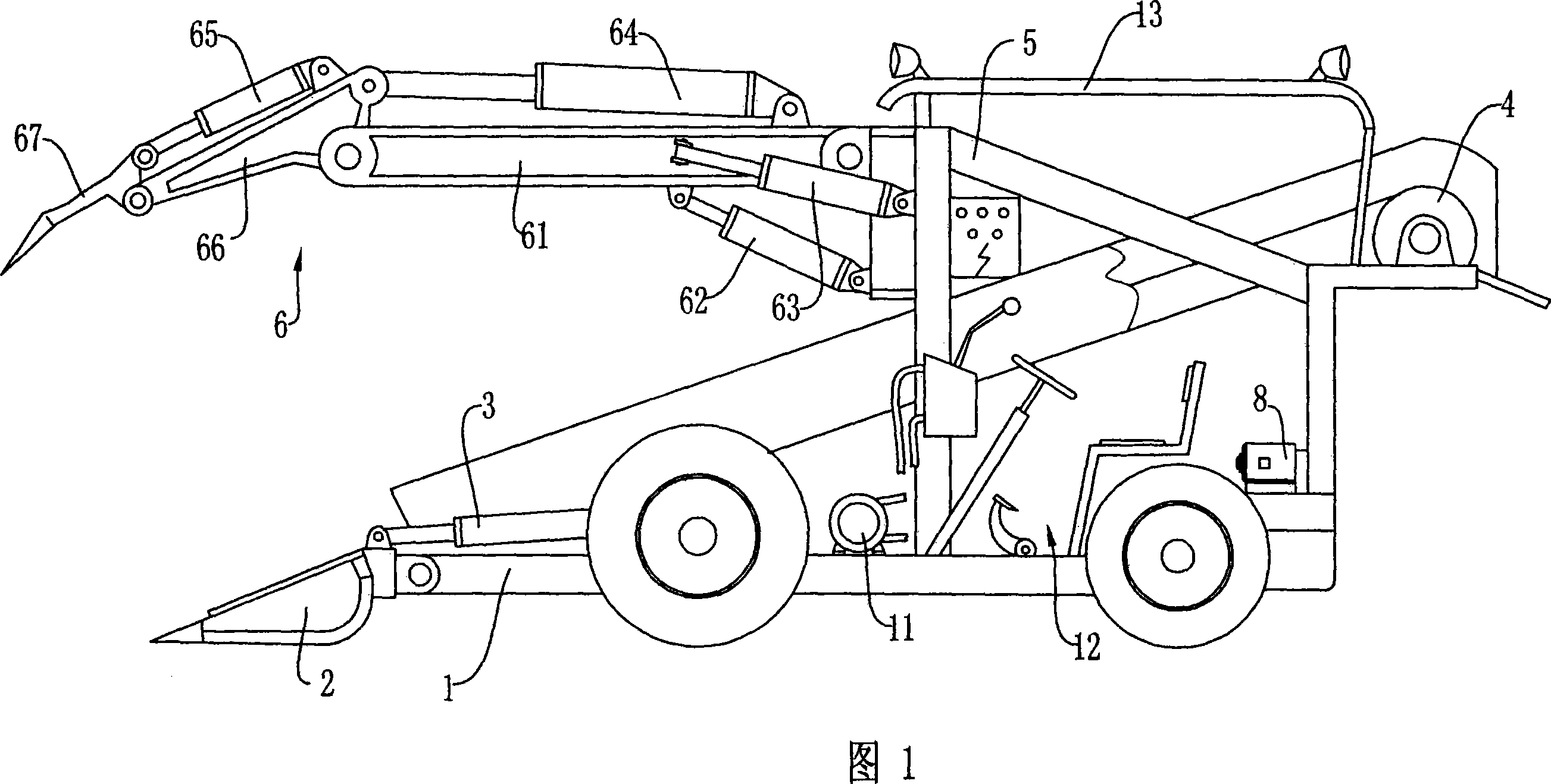
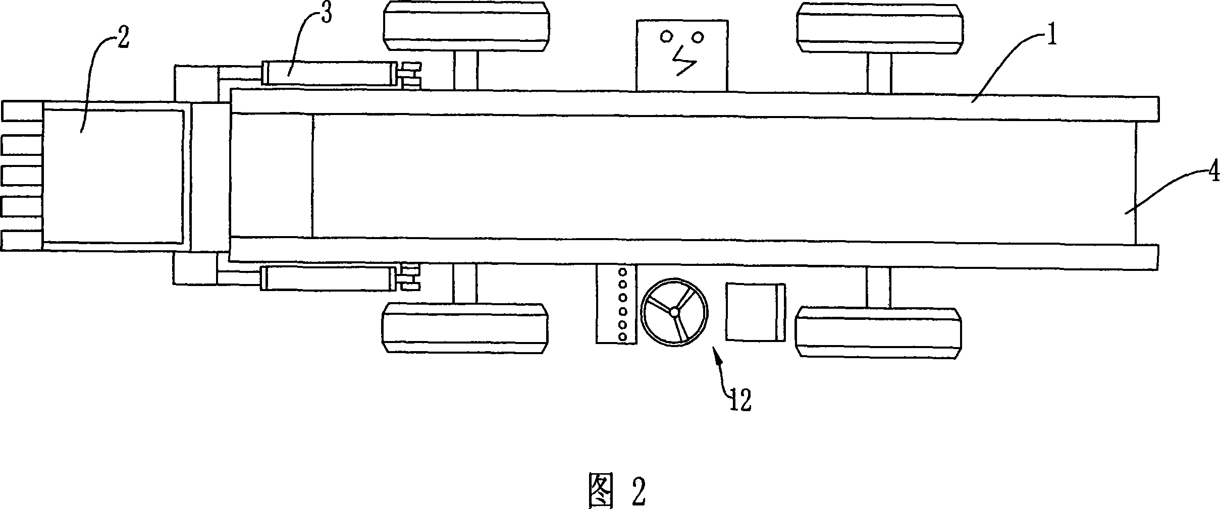
[0012] An ore shovel loader for a roadway, as shown in Figure 1, includes a traveling device 1 driven by a power device, a bucket 2 hinged at the front end of the traveling device 1, and installed between the bucket 2 and the traveling device 1 The first hydraulic cylinder 3; the conveying device 4 for transporting the ore scooped up by the bucket 2 from the front end of the traveling device 1 to the rear end of the traveling device 1, and the conveying device 4 is installed on the traveling device 1; fixed The frame 5 connected to the walking device 1 is installed on the rack 6, and the scraping device 6 is located above the bucket 2 and the conveying device 4.

[0013] Described pick-up device 6 comprises the big arm 61 that is hinged on described frame 5, the small arm 66 that is hinged on described big arm front end, the pick-up tooth 67 that is hinged on described small arm front end; And is hinged on frame 5 and The second hydraulic cylinder 62 that can make the boom 61 ...


PUM


Abstract

A stone forklift used for laneway includes a moving device drove by driving device, a bucket joint to the front of the moving device, the first hydro-cylinder installed between the bucket and the moving device, a transmission device installed on the moving device to transporting stone from the front to the back of the moving device, a rake stand fixed on the moving device to keep the rake over the bucket and the transmission device. Be designed for laneway, height of the forklift could be less than 1.5m, and width less than 1.4m, and multi hydro-cylinder could be used for easy moving of bucket and rake.

Description

technical field [0001] The invention relates to the technical field of mining machinery, in particular to a device for loading ore in a mine roadway. Background technique [0002] After the ore of the existing iron ore is manually blasted, because the roadway is too narrow and too short (the height of the roadway is generally 1.7m-1.8m, and the width is 1.6m-1.7m), and the ground is uneven, large machinery cannot be used, so , has always been manually loaded onto the ground truck, and then pulled to the hoist by the ground truck. The labor intensity of the workers is high, the efficiency is low, and the risk is high. Generally, 8 people are required to operate, and the working environment is very bad. Contents of the invention [0003] The technical problem to be solved by the present invention is to provide a roadway ore shovel loader to solve the problems of high labor intensity, low efficiency and high risk of manual loading ore. [0004] In order to solve the above-me...

Claims


Application Information

Patent Timeline
IPC IPC(8): E02F3/28E02F3/34E02F7/00E02F9/16
Inventor 燕连根李金科
Owner 燕连根
Why Eureka
Try Eureka