High-speed transmission correcting gear

A technology for correcting gears and high-speed transmission. It is applied to belts/chains/gears, components with teeth, portable lifting devices, etc., which can solve the problems of increasing the size and weight of the transmission gear pair, and the transmission structure is not compact enough to achieve improvement. Meshing conditions, improving strength and transmission efficiency, reducing wear effects

Inactive Publication Date: 2007-09-12
CHENDU KEDA AUTOMATION CONTROL ENG
View PDF0 Cites 4 Cited by
  • Summary
  • Abstract
  • Description
  • Claims
  • Application Information

AI Technical Summary

Problems solved by technology

However, there are still some limitations in standard gear transmission: (1) limited by undercutting, the number of teeth must not be less than Z min , so that the transmission structure is not compact enough; (2) It is not suitable for occasions where the installation center distance a' is not equal t

Method used


Image

  • High-speed transmission correcting gear
  • High-speed transmission correcting gear
  • High-speed transmission correcting gear

Examples


Example Embodiment

Examples:

When K=1 is selected, the pinion adopts the correction method of adding 1 to the number of teeth, and its geometric elements are as follows:

1.1 Index circle diameter d 1 =mZ 1

1.2 Pitch circle diameter d t1 =m(Z 1 +1)

1.3 Base circle diameter d 01 =mZ 1 cos20°

1.4 Base section t 0 =mπcos 20°

1.9 Pinion root circle diameter d i1 =(Z 1 +2ξ 1 -2.5)m

1.6 Z 1 ,Z 2 The actual meshing angle of the two gears a,

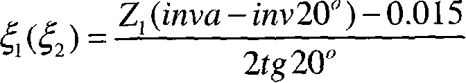
1.7 Z 1 ,Z 2 When the meshing gap between the two gears is 0.03m, the correction coefficient of the small gear and the large gear is

1.8 Full height of small gear teeth (full height of large gear teeth) h 1 (h 2 )=m[2.25-(ξ 1 -0.5)]

1.9 Pinion root circle diameter d i1 =(Z 1 +2ξ 1 -2.5)m

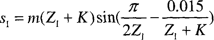
1.10 Fixed chord tooth thickness s 1 = m ( Z 1 + 1 ) sin ( π 2 Z ...


PUM


Abstract

The invention discloses a kind of high-speed drive modified gear used in the big drive ration occasion which can improve the engagement condition of gear at the same time decrease the number of teeth of gear. Its small gears adopt (Z1+K) to correct for the depth of tooth profile computation and treatment while the big gears adopt (Z2+(Z2/Z1)K) to correct for the depth of tooth profile computation and treatment with the coefficient K =0.5~1. Both the small and big gears are graduated handling according to the reality number of teeth. By correcting for the depth of tooth profile computation and treatment it can not only decrease the number of teeth, reduce line speed of the gear to reach the purpose of improving the rotational speed but also improve the engagement condition of gear and increase the abrasion of gear and increase the working life of gear also increase the strength of gear and the transmission efficiency. The invention offers the method of correction and treatment is simpler which brings convenience to design and process especially applicable for high-speed drive occasion.

Description

technical field The invention relates to a gear, especially a high-speed transmission correction gear used in the occasion of large transmission ratio. Background technique The involute standard gear design is simple in calculation and has good interchangeability. However, there are still some limitations in standard gear transmission: (1) limited by undercutting, the number of teeth must not be less than Z min , so that the transmission structure is not compact enough; (2) It is not suitable for occasions where the installation center distance a' is not equal to the standard center distance a. When a'<a, it cannot be installed. When a'>a, although it can be installed, it will cause excessive backlash and cause shock vibration, which will affect the stability of transmission; (3) when a pair of standard gears are driven, small The thickness of the dedendum of the gear is small and the meshing times are many, so the strength of the pinion is low, and the wear of the ...

Claims


Application Information

Patent Timeline
IPC IPC(8): F16H55/17
Inventor 郑飞蒋汉峰
Owner CHENDU KEDA AUTOMATION CONTROL ENG
Why Eureka
Try Eureka