
Electric lumbar support driver

A driver and lumbar support technology, which is applied to vehicle seats, special positions of vehicles, transportation and packaging, etc., can solve the problems of large size of the driver, insufficient rigidity of the worm gear, short service life, etc., and achieve small size and stable transmission output , long service life effect

Inactive Publication Date: 2017-03-15
ZHEJIANG YAHU AUTO PARTS
View PDF5 Cites 1 Cited by
  • Summary
  • Abstract
  • Description
  • Claims
  • Application Information

AI Technical Summary

Problems solved by technology

[0003] The main disadvantages of the above-mentioned electric adjustment driver are that since the motor drives the worm to rotate at a relatively high speed, in order to enable the wire wheel to slowly take in and out the wire, the outer diameter of the worm wheel is made larger, and the number of teeth of the inner and outer ring gears is relatively large. Many, the single tooth is thinner, in order to realize the deceleration of the first-stage transmission, such as 100:1, so the overall volume of the driver is larger, occupying a larger space, and the rigidity of the worm gear is not enough, which may result in a shorter service life and instability And other issues

Method used


Image

  • Electric lumbar support driver
  • Electric lumbar support driver

Examples


Embodiment Construction

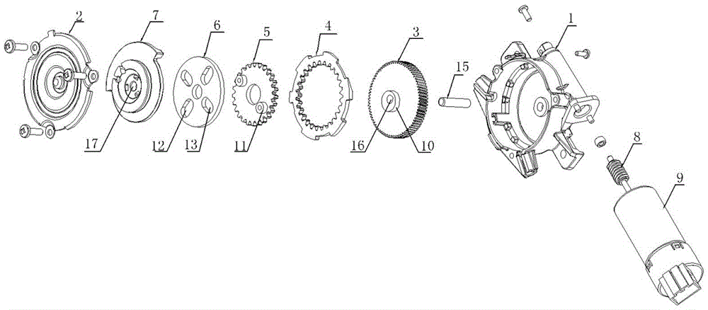
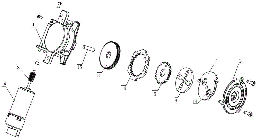
[0014] Accompanying drawing has shown structure of the present invention, further illustrates its relevant details below again in conjunction with accompanying drawing. The electric lumbar support driver includes a casing 1 and an end cover 2, the casing 1 and the end cover 2 are combined into a box body, the box body is provided with an outlet, and the box body is provided with a worm gear 3, a fixed ring gear 4, External gear 5, transmission disc 6 and cable disc 7; described worm gear 3 is driven and rotated by worm screw 8, and worm gear 3 is preferably a helical gear, which facilitates processing and control accuracy, and worm screw 8 is driven by a power source, which is preferably a motor 9, Worm screw 8 is connected with motor 9 shafts, and worm screw 8 is arranged on the worm screw 8 seat of shell 1 side; Described worm wheel 3 is provided with eccentric shaft 10, and external gear 5 is arranged on this eccentric shaft 10, and external gear 5 is provided with There is...


PUM


Abstract

The invention discloses an electric lumbar support driver. The electric lumbar support driver comprises a shell and an end cover, wherein the shell and the end cover are combined into a box body, and an outlet line is formed on the box body. The electric lumbar support driver is characterized in that a worm gear, a fixed gear ring, an external gear, a drive disc and an inhaul cable disc are arranged in the box body, the worm gear rotates by virtue of worm drive, a worm is driven by a power source, an eccentric shaft is arranged on the worm gear, the external gear is arranged on the eccentric shaft, a drive pin is arranged on the external gear, the fixed gear ring is fixedly arranged in the box body and is arranged outside the external gear to be eccentrically meshed with the external gear, the drive disc is arranged on the external gear, a first driving groove and a second driving groove are formed in the drive disc, the first driving groove is matched with the drive pin, the inhaul cable disc is rotatably arranged above the drive disc, a driving column is accordingly arranged on the inhaul cable disc, and the driving column is matched with the second driving groove. The electric lumbar support driver disclosed by the invention adopts stacked multi-drive, a large drive ratio is realized, the overall stability is better, and the service life is longer.

Description

technical field [0001] The invention relates to an improved invention of an electric lumbar support, in particular to an improved invention of an electric lumbar support driver. Background technique [0002] The car seat backrest adjustment system uses the cable to pull the backrest device to produce the effect of waist adjustment, including manual adjustment and electric adjustment. Among them, the working principle of the electric adjustment driver is to drive the worm gear through the high-speed motor At the same time, the worm gear is equipped with one or more planetary gear trains, and the planetary gear train is assembled on the wire wheel, and the wire wheel drives the cable to realize the deceleration between the motor and the cable to adjust the car seat. Backrest device. [0003] The main disadvantages of the above-mentioned electric adjustment driver are that since the motor drives the worm to rotate at a relatively high speed, in order to enable the wire wheel t...

Claims


Application Information

Patent Timeline
Patent Type & Authority Applications(China)
IPC IPC(8): B60N2/235
CPCB60N2/2231B60N2/224B60N2/235
Inventor 池仁虎舒易久
Owner ZHEJIANG YAHU AUTO PARTS
Learn More