
Processing and transferring apparatus

A technology for conveying devices and installation parts, which is applied in the direction of manufacturing tools, transportation and packaging, and manipulators. It can solve the problems of narrow moving range of the movable arm, difficult processing, and low degree of freedom of the movable arm. It achieves complex and precise machining, The effect of smooth movement and increased degree of freedom

Inactive Publication Date: 2007-09-12
HONDA MOTOR CO LTD
View PDF2 Cites 10 Cited by
  • Summary
  • Abstract
  • Description
  • Claims
  • Application Information

AI Technical Summary

Problems solved by technology

[0007] However, in any conventional example, the movable arm can only rotate in one axis direction with respect to the connection portion such as the base, so the movable range of the movable arm is narrow, and the degree of freedom of movement of the movable arm is also limited. High, so processing becomes difficult depending on the size or shape of the workpiece

Method used


Image

  • Processing and transferring apparatus
  • Processing and transferring apparatus
  • Processing and transferring apparatus

Examples


Embodiment Construction

[0022] Hereinafter, embodiments of the present invention will be described in detail based on the drawings.

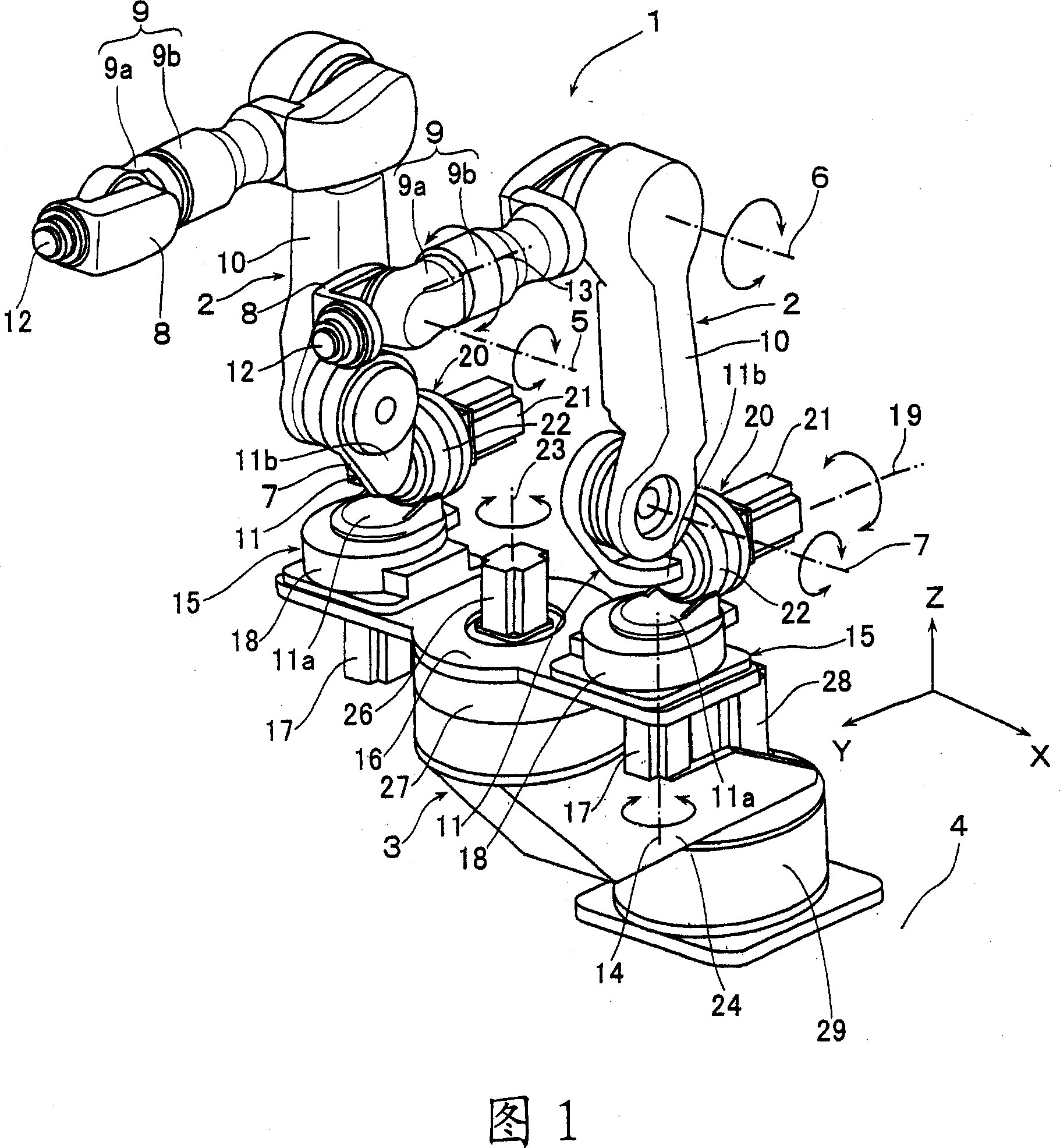
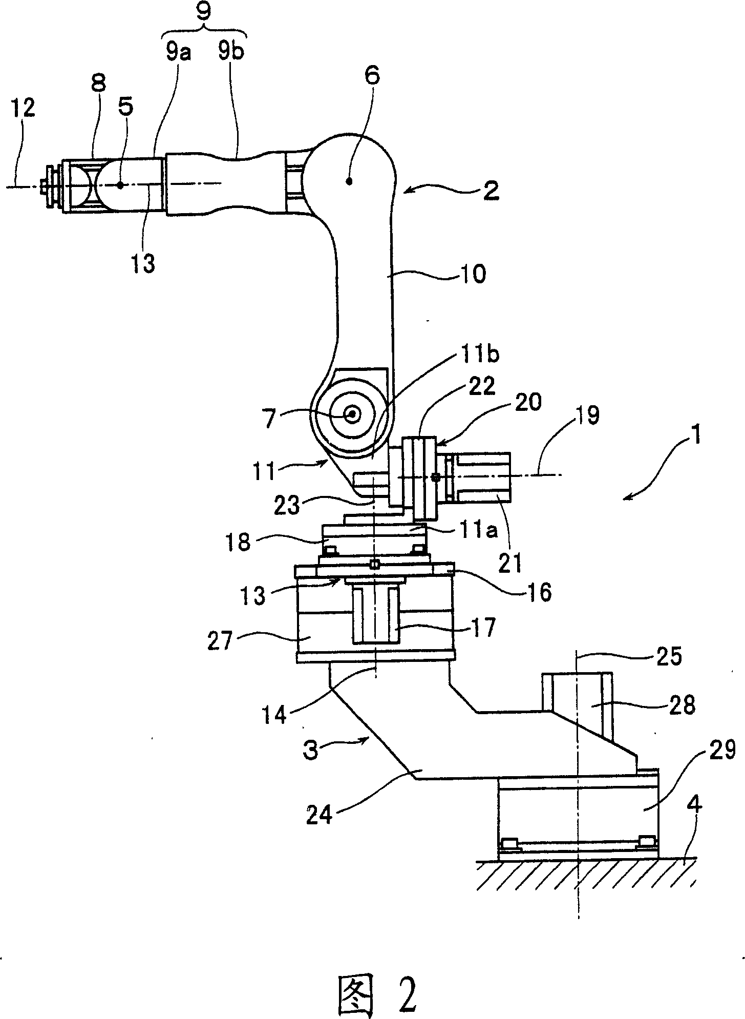
[0023] Fig. 1 is a perspective view showing the processing conveying device of the present invention, and Fig. 2 is a view of Fig. 1 viewed from the X-axis direction.

[0024] This processing conveying device 1 has a pair of multi-joint movable arms 2, and these movable arms 2 are mounted on a base 4 via a turning device 3. Each movable arm 2 has three joints that rotate around the rotation shafts 5, 6, and 7 facing the same direction (X-axis direction in FIG. 1).

[0025] For example, a bolt fastening device as a processing unit or a workpiece holding device (not shown) as a holding unit can be mounted on the joints connected by the joints so as to rotate around the rotation shaft 12 perpendicular to the rotation shafts 5, 6, and 7 of the joints. On the arm member 8 on the tip side among the arm members (8-11). The arm member 9 adjacent to the arm member 8 on the front en...


PUM


Abstract

A processing and transferring apparatus (1) is provided with a first turning means (15), which is provided between a base end of a movable arm (2) and a base plate (16) so as to turn the movable arm (2) with a rotating axis (14) vertical to rotating axes (5, 6, 7) of a joint of the movable arm (2) at the center; and a second turning means (20), which is provided on a base end side arm piece (11) of the movable arm (2) so as to turn the movable arm (2) with a rotating axis (19) vertical to both a rotating axis (14) of the turning means (15) and the rotating axes (5, 6, 7) of the joint at the center.

Description

Technical field [0001] The present invention relates to an apparatus for processing and conveying various kinds of workpieces. Specifically, it relates to a processing and conveying device having a unit for processing or holding a workpiece at the tip of a multi-joint movable arm. Background technique [0002] As such a device, for example, the devices shown in Patent Documents 1 and 2 are known. [0003] With the device described in Patent Document 1, the base end of the movable arm is supported on a base or the like so as to be rotatable about a horizontal rotation axis, and a plurality of rotation axes that can rotate about a vertical axis are provided on the movable arm. The freely rotating joint is provided with a processing unit at the tip of the movable arm. [0004] For the device described in Patent Document 2, the base end of the movable arm is supported on a base or the like so as to be rotatable about a vertical rotation axis, and a plurality of horizontal rotation ax...

Claims


Application Information

Patent Timeline
Patent Type & Authority Applications(China)
IPC IPC(8): B25J9/06B62D65/18B62D65/06
CPCB25J5/02B25J9/0087Y10T29/5177B25J9/06Y10T29/53974B25J9/0084B25J9/046
Inventor 大竹义人美和浩北村长久
Owner HONDA MOTOR CO LTD
Learn More