Accumulated-heat correction apparatus and accumulated-heat correction method for thermal head

A technology of a correction device and a correction method, which is applied in the directions of printing and digital output to the printing unit, etc., can solve the problems of color generation, insufficient correction amount, insufficient heat storage correction, etc., and achieve the effect of high-quality printing

Inactive Publication Date: 2007-09-19
MITSUBISHI ELECTRIC CORP
View PDF2 Cites 12 Cited by
  • Summary
  • Abstract
  • Description
  • Claims
  • Application Information

AI Technical Summary

Problems solved by technology

[0016] That is, the correction amount for line n+1 is insufficient because the correction amount is correction B-correction B', and the target printing density of line n+1 cannot be obtained
[0017] Specifically, there is a problem that heat storage correction is performed to make n+1 the density that does not produce color, but the heat storage correction is insufficient, resulting in slight color generation in printing density

Method used


Image

  • Accumulated-heat correction apparatus and accumulated-heat correction method for thermal head
  • Accumulated-heat correction apparatus and accumulated-heat correction method for thermal head
  • Accumulated-heat correction apparatus and accumulated-heat correction method for thermal head

Examples


Embodiment approach 1

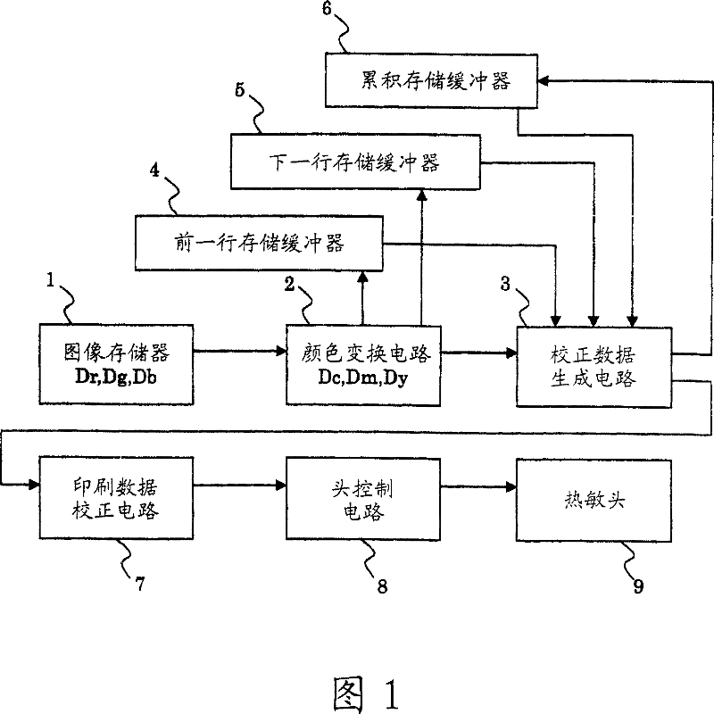
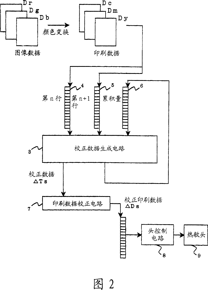
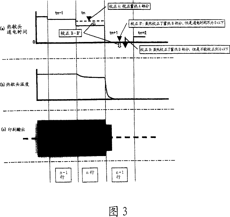
[0033] FIG. 1 is a circuit block diagram showing Embodiment 1 of the present invention. FIG. 2 is a diagram showing a flow of thermal storage correction processing performed by the circuit in the block diagram of FIG. 1 . FIG. 3 is a conceptual diagram showing a thermal storage correction method according to the first embodiment.

[0034] In FIG. 1 , an image memory 1 receives image data Dr, Dg, and Db of RGB colors from an external computer, etc., and a color conversion circuit 2 converts the image data Dr, Dg, and Db of each color into print data Dc, Dm, and Dy of each color. , and store these print data Dc, Dm, Dy in the current storage buffer 4 at the same time.

[0035] And at this point, the accumulated data up to the previous line n−1 is stored in the accumulated memory buffer 6 , and the print data of the next line n+1 is stored in the next memory buffer 5 .

[0036] The correction data generation circuit 3 reads the printing data of the current line n from the curre...


PUM


Abstract

The device for correcting thermal storage of the thermal head 5 which outputs printing data for every line to the thermal head 5 and controls an electrification time of the thermal head 5 on the basis of the printing data, is equipped with an accumulated data operating means which operates accumulated data caused by the thermal storage of the thermal head 5 up to the previous line n-1, a next line data operating means which operates the printing data of the next line n+1, a correction data generating means which operates correction data [Delta]Ts to correct the printing data of the present line n by using the accumulated data and the next line data, and a head controlling means which controls the electrification time of the thermal head 5 on the basis of the correction data [Delta]Ts generated by the correction data generating means.

Description

technical field [0001] The present invention relates to a heat storage correction device and a heat storage correction method for a thermal head of a thermal printer, a thermal sublimation printer, or the like. Background technique [0002] Such a conventional thermal storage correction method will be described in order. [0003] Fig. 6 is a conceptual diagram when there is no thermal storage correction. [0004] Figure 6(a) shows the power-on time of the thermal head. Usually the thermal head reaches the heat corresponding to the power-on time. FIG. 6( b ) is the temperature of the thermal head corresponding to the energization time of the thermal head in FIG. 6( a ). The printing density is usually obtained according to the temperature of the thermal head. FIG. 6( c ) is an example of print output at the time of energization of the thermal head in FIG. 6( a ), showing the print density state at the center. The energization time of the central part of the printed outpu...

Claims


Application Information

Patent Timeline
Patent Type & Authority Applications(China)
IPC IPC(8): B41J2/36
CPCB41J2/365G06F3/12
Inventor 畠中贵志
Owner MITSUBISHI ELECTRIC CORP
Why Eureka
Try Eureka