
Optical unit manufacturing method, optical unit, and forming apparatus

A technology of optical units and manufacturing methods, applied in optical elements, optical elements, optics, etc., can solve the problems of inability to withstand temperature, restrictions, etc.

Inactive Publication Date: 2007-09-19
SONY CORP
View PDF3 Cites 22 Cited by
  • Summary
  • Abstract
  • Description
  • Claims
  • Application Information

AI Technical Summary

Problems solved by technology

However, materials that can be used for lens barrels or frame units often include synthetic resins, and thus cannot withstand the temperatures used to form optical elements
When low-temperature softening glass is used as an optical material, the molding temperature of preformed glass under pressure is also as high as 400 degrees or more, so this method imposes restrictions on the materials used for lens barrels or frame units

Method used


Image

  • Optical unit manufacturing method, optical unit, and forming apparatus
  • Optical unit manufacturing method, optical unit, and forming apparatus
  • Optical unit manufacturing method, optical unit, and forming apparatus

Examples


Embodiment Construction

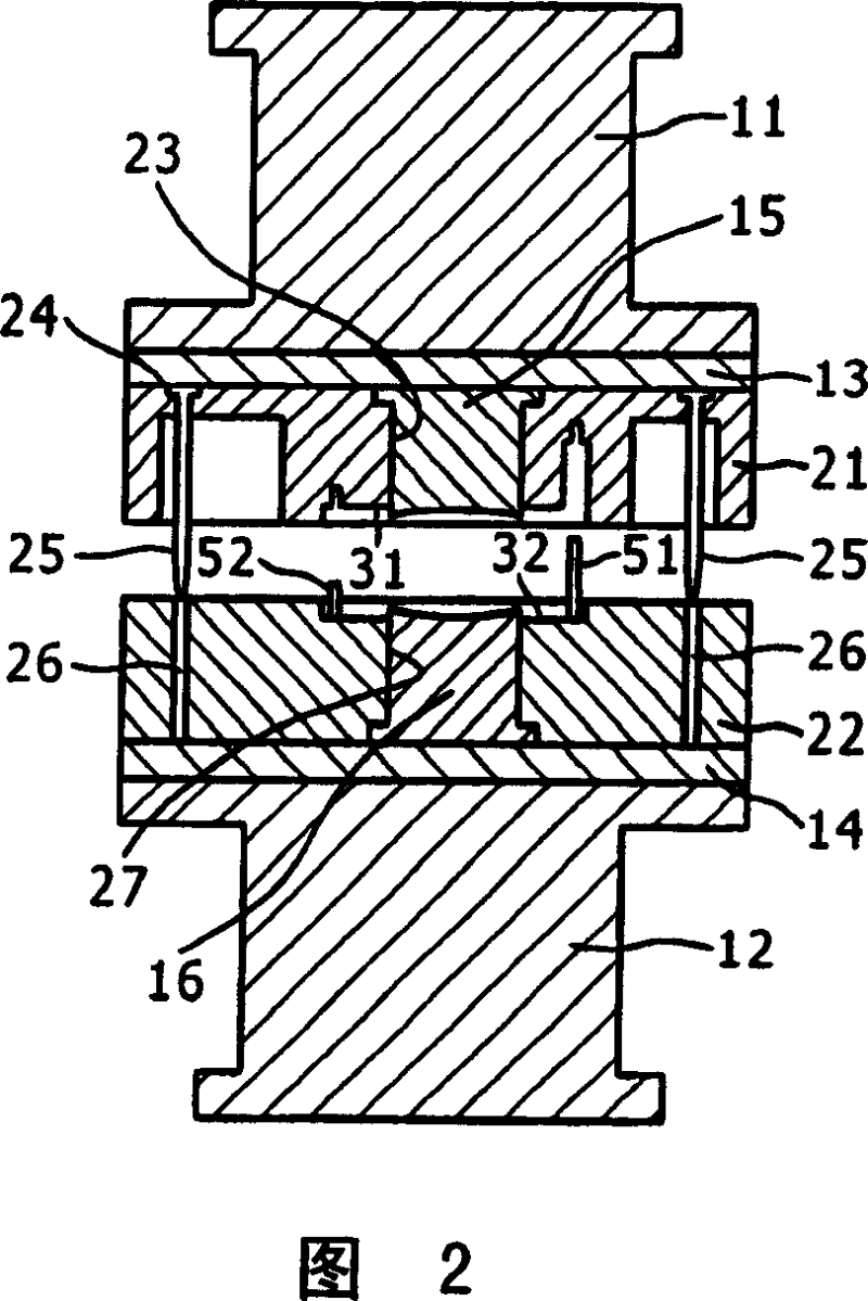
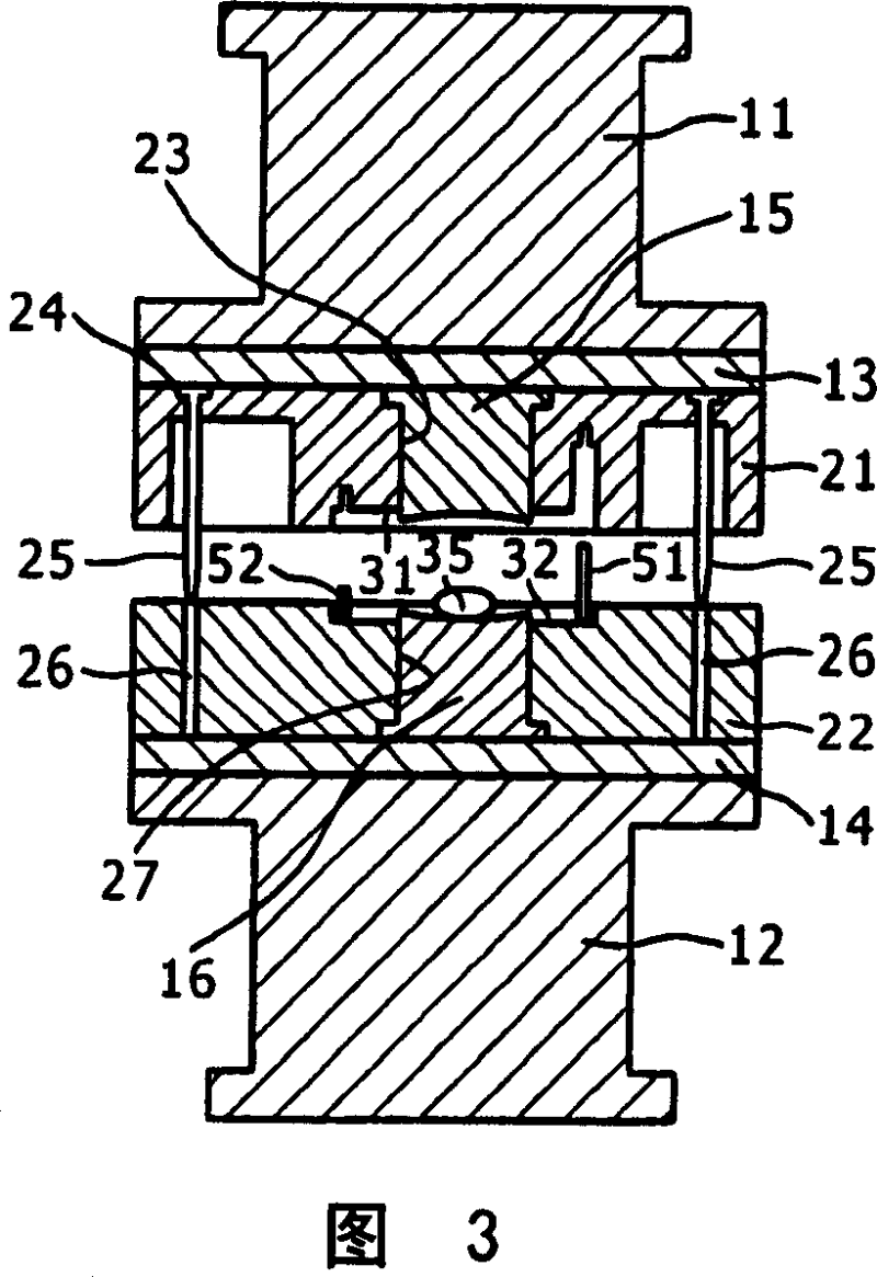
[0030] 1 and 2 illustrate a forming device for manufacturing an optical unit according to an embodiment of the present invention, and the shown forming device has an upper shaft 11 and a lower shaft 12 . The lower surface of the upper shaft 11 is provided with a template 13 , while the upper surface of the lower shaft 12 is provided with a template 14 . Furthermore, these templates 13 and 14 are adapted to hold the upper part 15 and the lower part 16 respectively.

[0031] The upper part 15 and the lower part 16 , both contained in the mold, are configured to be held by the upper and lower cylindrical parts 21 and 22 . The upper cylindrical part 21 has a circular central hole 23 in its central part, allowing the upper part 15 to be secured after it has been placed in the central hole 23 . The upper cylindrical member 21 also has a pair of insertion holes 24 which are arranged in a symmetrical configuration around the central hole 23 . A pair of positioning pins 25 inserted o...


PUM


Abstract

There is provided an optical unit manufacturing method in which an optical element is obtained by giving compression to an optical material using a mold after thermal softening of the optical material, and uniting of a frame unit with the optical element is required. The optical unit manufacturing method includes a step of forming the frame unit as an integral part of the optical element with reference to a position of the mold while holding the optical element without opening the mold after forming of the optical element .

Description

[0001] Cross References to Related Applications [0002] This application contains subject matter related to Japanese Patent Application JP2005-177024 filed in the Japan Patent Office on Jun. 16, 2005, the entire content of which is hereby incorporated by reference. field of invention [0003] The invention relates to a manufacturing method of an optical unit, an optical unit, and a mold thereof. More specifically, the present invention relates to a manufacturing method of an optical unit in which an optical element combined with a frame unit is obtained by performing compression (press molding) on ​​the optical material in a mold after thermally softening the optical material, An optical unit obtained by the above method, and a forming device for forming the above optical unit. Background technique [0004] Small high-performance optical lenses are used as optical systems of electronic image capturing devices such as electronic still cameras, electronic v...

Claims


Application Information

Patent Timeline
Patent Type & Authority Applications(China)
IPC IPC(8): G02B3/00C03B11/08C03B33/04B29D11/00
CPCC03B11/08B29L2012/00G02B7/10C03B2215/79B29C43/14B29C45/16B29C2043/3618B29L2011/0016B29C43/021C03B2215/60B29C43/00
Inventor 山道伸浩
Owner SONY CORP
Learn More