
Lens unit

A lens unit and lens technology, applied in optical components, optics, instruments, etc., can solve the problems of poor machinability of the first lens, increase of manufacturing cost, and lens unit not suitable for mass production, etc.

Inactive Publication Date: 2007-09-19
SONY GRP CORP
View PDF2 Cites 18 Cited by
  • Summary
  • Abstract
  • Description
  • Claims
  • Application Information

AI Technical Summary

Problems solved by technology

In addition, since the image-side surface (second surface) of the first lens constituting the front group should be made substantially hemispherical, the workability of the first lens deteriorates, thereby increasing the manufacturing cost, making this lens unit unsuitable for mass production

Method used


Image

  • Lens unit
  • Lens unit
  • Lens unit

Examples


Embodiment 1

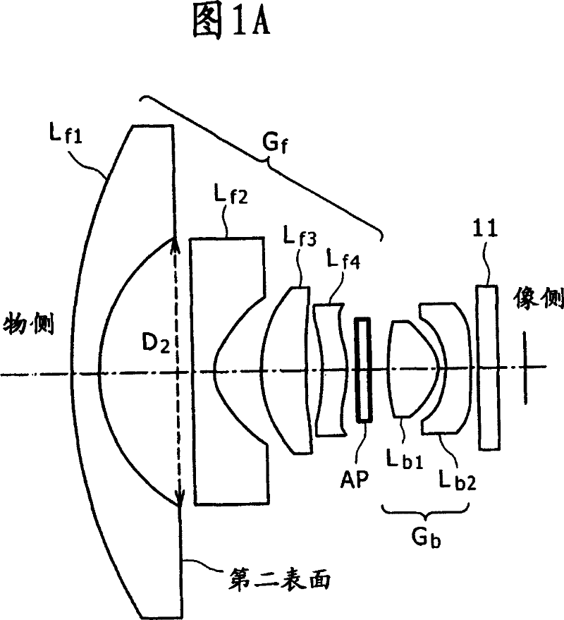
[0067] Embodiment 1 belongs to a lens unit according to an embodiment of the present invention, especially a lens unit according to a first mode of the present invention, more specifically, a fisheye lens unit. A conceptual diagram of a lens unit according to Embodiment 1 is shown in FIG. 1A. The lens unit in Embodiment 1 is a two-group six-lens lens unit including a front group G composed of lenses in order from the object side to the image side f , aperture AP and rear group G composed of lenses b . Front group G f In order from the object side to the image side include:

[0068] (A-1) First lens L having negative (having negative power) meniscus f1 ;

[0069] (A-2) Negative (having negative power) second lens L made of plastic and having an aspherical surface f2 ;

[0070] (A-3) Positive (having positive power) third lens L f3 ;as well as

[0071] (A-4) Positive (having positive power) fourth lens L f4 .

[0072] In addition, the latter group G b In order from t...

Embodiment 2

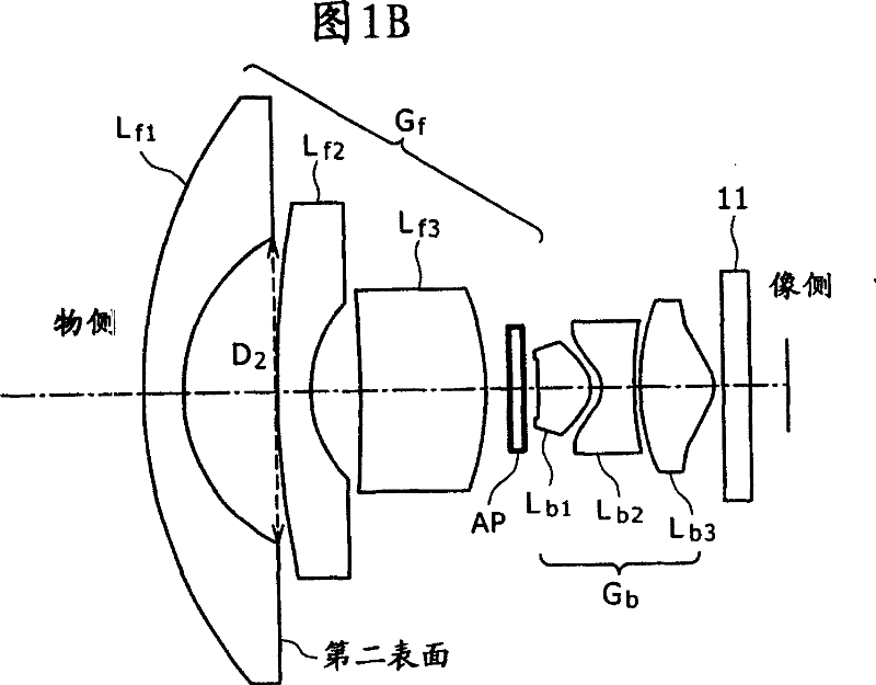
[0100] Embodiment 2 is a modification of Embodiment 1, which belongs to the lens unit according to the second mode of the present invention, specifically, a fisheye lens unit. A conceptual diagram of a lens unit in Example 2 is shown in FIG. 1B . The lens unit in Embodiment 2 is also a lens unit of 6 lenses in 2 groups, including a front group G composed of lenses in order from the object side to the image side f , the rear group G composed of aperture AP and lens b . Front group G f In order from the object side to the image side include:

[0101] (A-1) First lens L having negative (having negative power) meniscus f1 ;

[0102] (A-2) Negative (having negative power) second lens L made of plastic and having an aspherical surface f2 ;as well as

[0103] (A-3) Positive (having positive power) third lens L f3 . In addition, the latter group G b include:

[0104] (B-1) Positive (having positive power) first lens L b1 ;

[0105] (B-2) Negative (having negative power) s...


PUM


Abstract

A lens unit includes a front group, a stop, and a rear group, in order from the object side toward the image side. The front group includes at least: a first lens having a negative meniscus shape; a negative second lens formed from a plastic and having an aspherical surface; and a positive third lens, in order from the object side toward the image side. The rear group includes at least: a positive first lens; and a negative second lens, in order from the object side toward the image side.

Description

[0001] Cross-references to related applications [0002] The present application contains subject matter related to Japanese Patent Application JP 2006-075531 filed in the Japan Patent Office on Mar. 17, 2006, the entire content of which is hereby incorporated by reference. technical field [0003] The present invention relates to a lens unit. Background technique [0004] As a lens unit suitable for inclusion in an image pickup device having a small image pickup device or the like, such as a fisheye lens unit, a fisheye lens unit having four lenses in total is known, for example, Japanese Patent Laid-Open Publication 2005-227426 (hereinafter referred to as Patent Document 1). [0005] However, in such a fisheye lens unit disclosed in Patent Document 1, in order to obtain good optical characteristics, the total optical length should be increased to be equal to or greater than 15 mm. In addition, when trying to shorten the total optical length, the radius of curvature R of ...

Claims


Application Information

Patent Timeline
Patent Type & Authority Applications(China)
IPC IPC(8): G02B13/00G02B13/18
CPCG02B13/04G02B9/62G02B13/0045G02B9/60
Inventor 马场友彦
Owner SONY GRP CORP
Learn More