Eureka AIR delivers breakthrough ideas for toughest innovation challenges, trusted by R&D personnel around the world.

Heat abstractor

A technology of heat dissipation device and radiator, applied in the direction of cooling/ventilation/heating transformation, etc., can solve the problems of heat dissipation efficiency, easy damage of heat pipes, and insufficient structure, so as to achieve the effect of enhancing stability and reducing stress burden.

Active Publication Date: 2007-09-19
CHAMP TECH OPTICAL FOSHAN
View PDF1 Cites 0 Cited by
  • Summary
  • Abstract
  • Description
  • Claims
  • Application Information

AI Technical Summary

Problems solved by technology

With the improvement of component integration, the heat generated by electronic components is also increasing. In the past, a single heat sink has been difficult to meet the heat dissipation requirements. The new combined double heat sink has been gradually applied, as disclosed in U.S. Patent No. 2003 / 0183373 A1 A heat dissipation device, the heat dissipation device includes first and second heat sinks and a heat pipe that conducts heat from the first heat sink to the second heat sink, however, the two heat sinks are only connected by heat pipes, and the structure is not enough Strong, the heat pipe is easily damaged when subjected to external impact, and the heat dissipation efficiency of the heat pipe and even the entire heat dissipation device will be affected

Method used


Image

  • Heat abstractor
  • Heat abstractor

Examples


Embodiment Construction

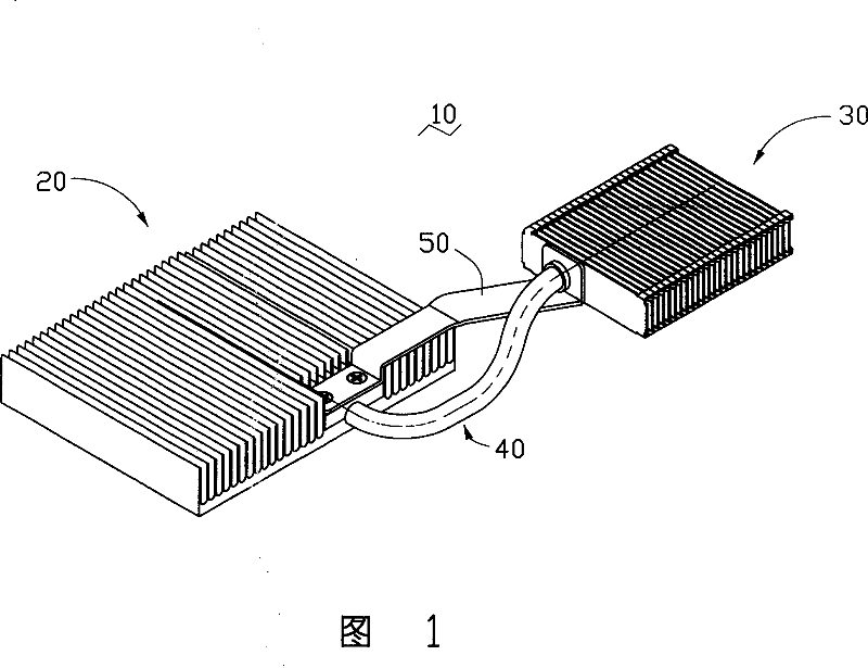
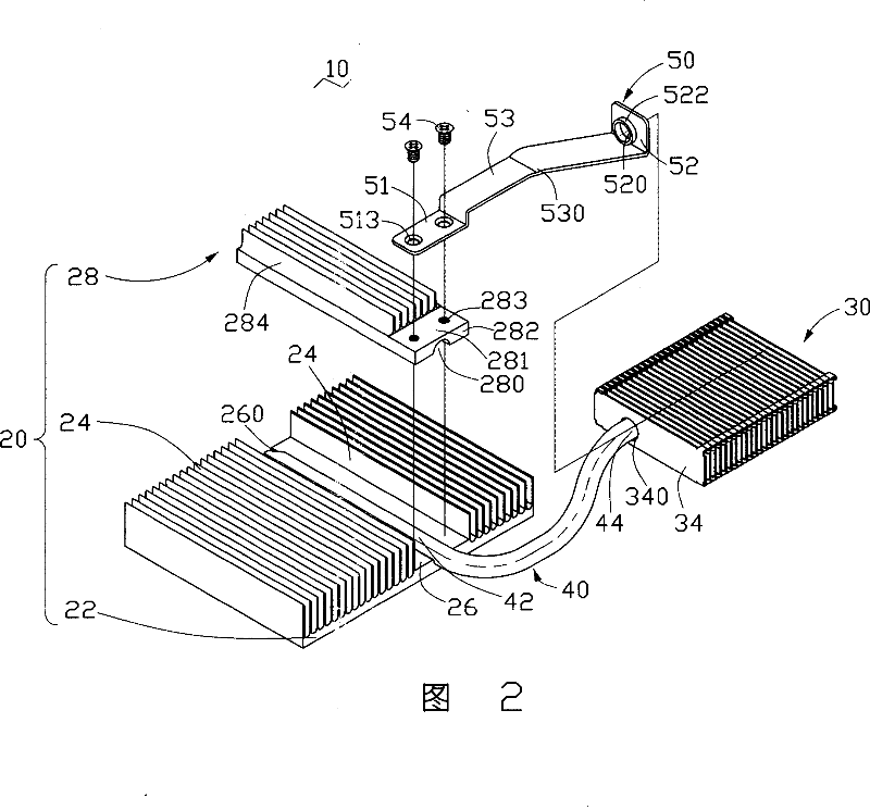
[0009] Referring to Fig. 1 and Fig. 2, the heat dissipation device 10 includes a first radiator 20, a second radiator 30, a heat pipe 40 and a protective frame 50 for conducting heat from the first radiator 20 to the second radiator 30 , the protective frame 50 is connected with the first heat sink 20 , the second heat sink 30 and the heat pipe 40 at the same time, so as to enhance the structural stability of the entire heat sink 10 .

[0010] The heat pipe 40 is curved and includes a heat absorbing portion 42 and a heat releasing portion 44 .

[0011] The first heat sink 20 includes a base 22 , two sets of cooling fins 24 extending upward from the base 22 and spaced apart from each other, and a separation block 28 installed between the two sets of cooling fins 24 . The two sets of cooling fins 24 on the first heat sink 20 are separated by a connecting portion 26 . A groove 260 is formed in the center of the top of the connecting portion 26 for accommodating the heat absorbing...


PUM


Abstract

The present inventive cooling device includes a first radiator, a second radiator and a heat pipe connecting the first and the second radiators. The cooling device has a protection frame, which has a first terminal and a second terminal, the first terminal of the protection frame connected with the first radiator, and the second terminal connected with the second radiator. The cooling device reduces stress burden of the heat pipe, and enhances the structure stability of the heat cooling devic by adding a protection frame respectively connected to the two radiators.

Description

【Technical field】 [0001] The invention relates to a heat dissipation device, in particular to a heat dissipation device for electronic components. 【Background technique】 [0002] Usually, a heat sink is installed on the surface of the electronic component, so as to discharge the heat generated by it in time, so as to maintain its normal and stable operation. With the improvement of component integration, the heat generated by electronic components is also increasing. In the past, a single heat sink has been difficult to meet the heat dissipation requirements. The new combined double heat sink has been gradually applied, as disclosed in U.S. Patent No. 2003 / 0183373 A1 A heat dissipation device, the heat dissipation device includes first and second heat sinks and a heat pipe that conducts heat from the first heat sink to the second heat sink, however, the two heat sinks are only connected by heat pipes, and the structure is not enough Strong, when subjected to external impact...

Claims


Application Information

Patent Timeline
Patent Type & Authority Applications(China)
IPC IPC(8): H05K7/20
Inventor 陈永东杨波勇余光翁世勋陈俊吉
Owner CHAMP TECH OPTICAL FOSHAN
Why Eureka
Eureka Blog
Learn More